

Flying spot formation device and design method theref
A design method and flying point technology, applied in the field of radiation imaging, can solve problems such as potential safety hazards, cracking of shields, and low scanning efficiency, and achieve the effects of improved scanning effects, improved hardware performance, and high scanning efficiency
- Summary
- Abstract
- Description
- Claims
- Application Information
AI Technical Summary
Problems solved by technology
Method used
Image

Examples
Embodiment Construction
[0022] The technical solutions of the present invention will be described in detail below in conjunction with the accompanying drawings and specific embodiments.
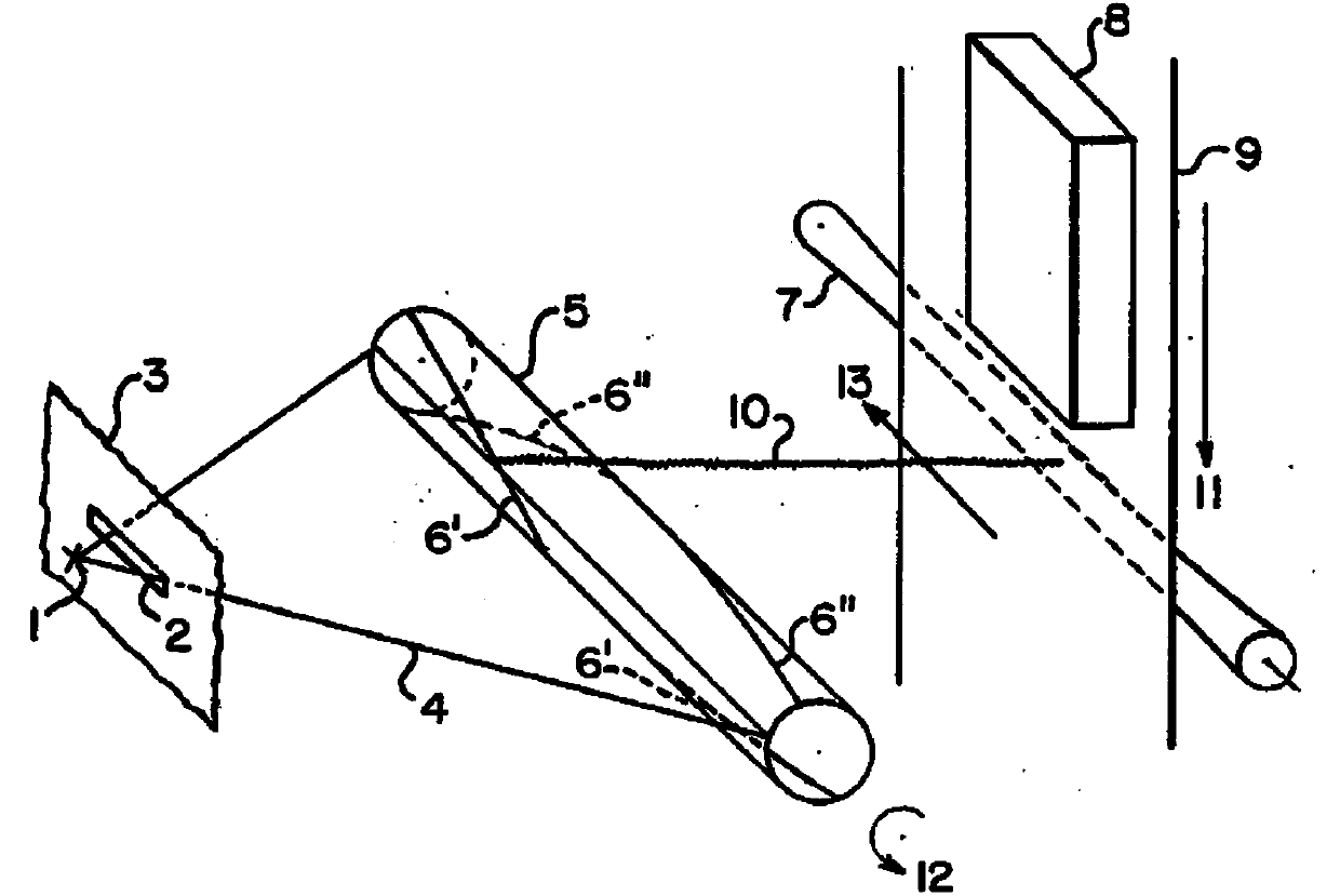
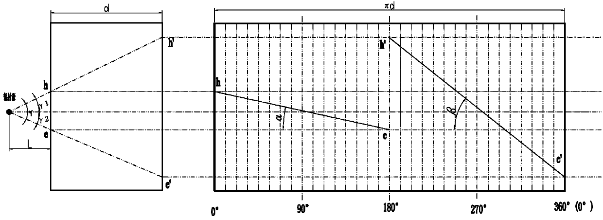
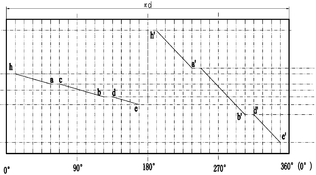
[0023] According to the principle of flying spot formation, the incident slot and the exit slot on the shield in the flying spot formation device correspond to each other, and the corresponding relationship between the two can be described as: the size and arrangement of the incident slot and the exit slot are such that During the rotation of the shielding body, at a certain moment, the focus of the radiation source, the incident point and the corresponding exit point form a straight line. For example, refer to figure 2 In the middle left picture, at time t1, the focus P of the radiation source, the incident point h and the corresponding exit point h' form a straight line; after the shield rotates 180° (at time t2), the focus P of the radiation source, the incident point e and the corresponding exit point Point e'...
PUM
 Abstract
Description
Claims
Application Information