Position identification device of telescope

A technology for identifying devices and microscopes, which is applied in the field of microscopes, can solve problems such as power-taking trouble, complex structure, device failure, etc., and achieve the effect of avoiding complicated and messy wiring and good reliability

Inactive Publication Date: 2014-12-17
MOTIC CHINA GRP CO LTD
View PDF6 Cites 9 Cited by
  • Summary
  • Abstract
  • Description
  • Claims
  • Application Information

AI Technical Summary

Problems solved by technology

When the Hall sensor moves together with the working position switching device, it will become more troublesome to take power, and it may be necessary to drag the wires to move together or use brushes, etc.
However, in the objective lens converter or the fluorescence filter cube turret of the microscope, the converter or the turret can rotate infinitely in one direction. If the existing technology is used, the wires dragged by the Hall sensor will also follow the converter or the turret. Rotating the turntable and winding it round and round may cause the wire to be broken or the plug to be pulled out, and the device will fail, and if a brush is used, the structure will become more complicated.

Method used


Image

  • Position identification device of telescope
  • Position identification device of telescope

Examples


Embodiment approach 1

[0027] Embodiment 1: Turntable structure

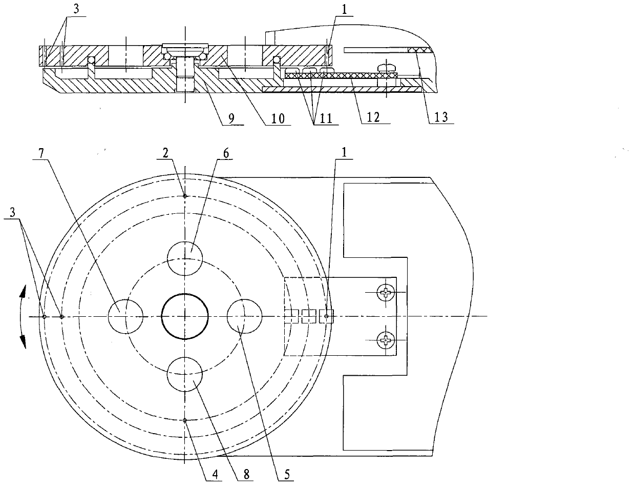
[0028] Such as figure 1 As shown, the turntable 10 is a working position switching device, and 5, 6, 7, and 8 are its four working positions. Each working position is preset with a unique binary code. 3, 4 to represent.

[0029] For comprehensive position measurement, multiple Hall sensors 11 can be selected, and three Hall sensors 11 are selected to be welded on the Hall sensor group 12 in the two embodiments of this patent. The Hall sensor group 12 is installed on the fixed plate 9 and remains stationary, and each Hall sensor 11 corresponds to a one-bit code of the current working position.

[0030] figure 1 When the turntable 10 rotates to a certain working position, the corresponding magnet group representing the coding of the working position will turn to the position corresponding to the Hall sensor group 12, and the control circuit 13 will pass the level signal induced by the Hall sensor 11 , to obtain the code of the magne...

Embodiment approach 2

[0031] Implementation Mode 2: Skateboard Structural Form

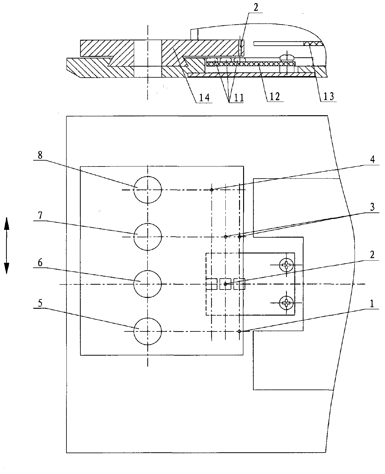
[0032] Such as figure 2 As shown, the slide plate 14 is a working position switching device, 5, 6, 7, and 8 are its four working positions, each working position is preset with a unique binary code, and the magnet groups 1 and 2 fixed on the slide plate 14 , 3, 4 to represent.

[0033] Three Hall sensors 11 are welded on the Hall sensor group 12 . The Hall sensor group 12 is installed on the fixed plate 9 and remains motionless. Each Hall sensor 11 corresponds to a bit code of the current working position.

[0034] figure 2 When the slide plate 14 is pulled to a certain working position, the corresponding magnet group representing the coding of the working position will move to the position corresponding to the Hall sensor group 12, and the control circuit 13 senses the level signal through the Hall sensor 11, The current working position can be identified by obtaining the code of the magnet group and comparing ...


PUM


Abstract

The invention discloses a position identification device of a telescope. The position identification device is composed of a work position switching device, a plurality of differently arranged magnet sets, a fixing board, a Hall sensor set and a control circuit, wherein the work position switching device is provided with a plurality of work positions linearly or circumferentially, and each work position is provided with an exclusive binary code indicated by one magnet set; the magnet sets are mounted on the work position switching position, and the Hall sensor set is provided with a plurality of Hall sensors. During working, the work position switching device moves to a certain work position, the magnet sets of the codes of the work positions moves or rotates to the positions corresponding to the Hall sensor set, and the control circuit senses level signals through the Hall sensors to acquire the codes of the magnet sets to be compared with the codes of the preset work positions, thus, the current work positions can be identified. The position identification device adopts a non-contact identification way, so wear and sound caused by contact identification are avoided, and wiring is simple and high in reliability.

Description

technical field [0001] The invention relates to the field of microscopes, in particular to a device for identifying the position of a microscope. Background technique [0002] When using a microscope for observation, it is often necessary to switch between different objective lenses according to observation needs. Due to the different parameters such as magnification and aperture angle of each objective lens, the requirements for the brightness of the lighting source are also different. In the traditional method, each time an objective lens is switched, the brightness of the illumination source needs to be manually adjusted. If the optimal brightness matched by each objective lens can be preset and stored in the microscope system, and the microscope system will automatically adjust to the optimal brightness when switching the objective lens, it will bring a lot of convenience to the operation of the microscope, and it can also avoid the need to change the objective lens. C...

Claims


Application Information

Patent Timeline
Patent Type & Authority Applications(China)
IPC IPC(8): G02B21/00
Inventor 陶素华陈木旺陈东明
Owner MOTIC CHINA GRP CO LTD
Why Eureka
Try Eureka