Device and method for thermal image analysis

A technology of image analysis and thermal image, which is applied in the field of thermal image shooting devices and thermal image analysis devices, can solve problems such as inconvenient operation, no mention of effective methods for rapid analysis and processing, troubles, etc.

Inactive Publication Date: 2014-12-17
MISSION INFRARED ELECTRO OPTICS TECH
View PDF4 Cites 7 Cited by
  • Summary
  • Abstract
  • Description
  • Claims
  • Application Information

AI Technical Summary

Problems solved by technology

[0005] However, when users need to quickly understand the states of these objects in a large number of thermal image files, the above-mentioned prior art is still very inconvenient and cumbersome to operate.
[0006] In addition, such as the thermal image data stream files containing various objects obtained by dynamic shooting, the existing technology does not mention an effective method for rapid analysis and processing

Method used


Image

  • Device and method for thermal image analysis
  • Device and method for thermal image analysis
  • Device and method for thermal image analysis

Examples


Embodiment 1

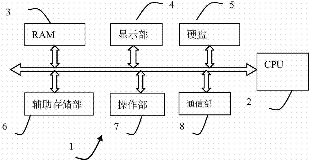
[0027] Example 1, figure 1 It is a block diagram of the electrical structure of the thermal image analysis device 1 of the present invention; figure 2 The outline drawing of the shown thermal image analysis device 1;

[0028] The thermal image analysis device 1 of this embodiment has a CPU2 for overall control, a RAM3 connected to the CPU2 through a bus, a display part 4, a hard disk 5, an auxiliary storage part 6, an operation part 7 and a communication part 8.

[0029] RAM3 temporarily stores various data temporarily generated by CPU2 executing programs.

[0030] The display unit 4 is, for example, a liquid crystal display, and performs display under the control of the CPU 2 . Not limited thereto, the display unit 4 may also be another display connected to the thermal image processing device 1 , and the electrical structure of the thermal image processing device 1 itself may not have a display.

[0031] Programs for control and various data used for control are stored in...

Embodiment 2

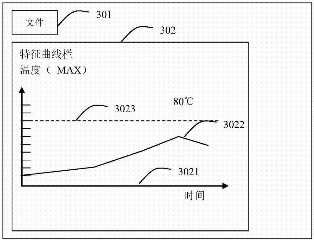
[0080] see Figure 5 , to describe a display example of the display interface of the thermal image analysis device 1 of the second embodiment.

[0081] Including, the file 301 menu item is used to select the thermal image file to be analyzed from the storage medium such as the hard disk 5;

[0082] The filter condition 302 menu item is used to set the filter condition of the thermal image data frame related to the generated characteristic curve. The filter condition can be based on the number of sampling frames, sampling interval, all thermal image picture files, frame additional information or related information , one or more of the characteristic data, as a filter condition, to filter the thermal image data frame contained in the selected thermal image file, and obtain the specified frame.

[0083] The feature analysis condition 303 menu item is used to set the feature analysis condition related to the generation of the characteristic curve. The feature analysis condition ...


PUM


Abstract

A thermal image analysis device and a thermal image analysis method. The thermal image analysis method comprises: according to a plurality of selected thermal image data frames, performing analysis to obtain feature data of a specified frame; and based on frame time-sequence information about the specified frame and the feature data of the specified frame obtained by analysis, forming in a feature curvilinear coordinate system a feature curve formed by feature points or by connecting the feature points. The thermal image analysis device and the thermal image analysis method enable an observer to rapidly and directly know conditions of shot objects corresponding to these thermal image data frames by observing the feature curve.

Description

technical field [0001] The thermal image analysis device and the thermal image analysis method of the present invention relate to the thermal image analysis device, the thermal image shooting device, and the application field of infrared detection. Background technique [0002] As a well-known technology, thermal imaging data frames captured on site are recorded by a thermal imaging device to generate a thermal image file, which is convenient for subsequent thermal field analysis of the subject to evaluate the state of the subject. The thermal image file can be divided into a thermal image file and a thermal image data stream file, the thermal image file contains a frame of thermal image data frame; and the thermal image data stream file can contain two or more thermal image data frames . [0003] At present, for the thermal image file obtained by shooting, when analyzing, the analysis software is usually used to open a single thermal image file, and then perform correspond...

Claims


Application Information

Patent Timeline
Patent Type & Authority Applications(China)
IPC IPC(8): G06T7/00G01N25/72H04N5/33
CPCG06T11/206G06T7/11G06T2207/10048
Inventor 王浩
Owner MISSION INFRARED ELECTRO OPTICS TECH
Why Eureka
Try Eureka