
Charge and discharge circuit based on lifting work lights

A charging and discharging circuit and a technology for lifting and lowering work lights, which are applied in the direction of battery circuit devices, circuit devices, collectors, etc., and can solve the problems of digital frequency conversion generators working time and power cannot be fully utilized.

Active Publication Date: 2016-05-18
SHENZHEN OCEANS KING LIGHTING ENG CO LTD +1
View PDF7 Cites 0 Cited by
  • Summary
  • Abstract
  • Description
  • Claims
  • Application Information

AI Technical Summary

Problems solved by technology

[0004] Based on this, it is necessary to provide a charging and discharging circuit based on lifting work lights that can prolong the working time of lifting work lights and make full use of the power of digital frequency conversion generators in order to solve the problems of the working time limit and power of digital variable frequency generators.

Method used


Image

  • Charge and discharge circuit based on lifting work lights
  • Charge and discharge circuit based on lifting work lights

Examples


Embodiment Construction

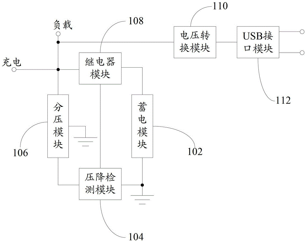
[0022] like figure 1 As shown, it is a block diagram of the charging and discharging circuit based on the lifting work light.

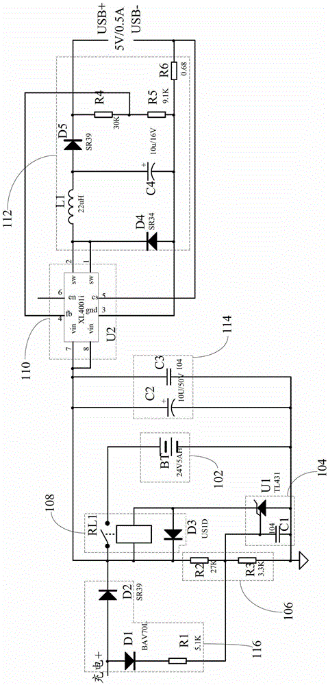
[0023] A charging and discharging circuit based on lifting work lights, used to discharge work lights and external electronic equipment, including: a power storage module 102 for receiving charging from a power generation module (not shown in the figure), and a power storage module 102 for detecting The voltage drop detection module 104, the voltage divider module 106 for dividing the voltage of the power storage module 102 to the voltage drop detection module 104, the relay module 108 for controlling the external power supply of the power storage module 102, and the A voltage conversion module 110 for converting the voltage of the power storage module 102 into a USB standard charging voltage and a USB interface module 112 for providing a connection port for a USB data line.

[0024] The detection end of the voltage drop detection module 104 is elect...


PUM


Abstract

The invention provides a charge-discharge circuit based on a lifting work light for discharging the work light and an external electronic apparatus. The charge-discharge circuit comprises: a power storage module for receiving the power supplied by a power generating module; a voltage drop detection module for detecting the voltage of the power storage module; a voltage divider module for dividing the voltage of the power storage module to the voltage drop detection module; a relay module for controlling the power supply of the power storage module to the external apparatus, a voltage conversion module for converting the voltage of the power storage module into a standard USB charging voltage; and a USB interface module for providing connection ports for USB data lines. The backward stage of the power storage module is joined to the voltage conversion module and the USB interface module so that the voltage of the power storage module is capable of being output to the external electronic apparatus by the USB, in order to take full advantage of the electricity generated by the power generating module. Furthermore, the power storage module is capable of storing the electricity, therefore can supply power to a lamp if the power generating module stops power generation, in order to prolong the working time of the lifting work light.

Description

technical field [0001] The invention relates to a lifting work light, in particular to a charging and discharging circuit based on a lifting work light for external discharge. Background technique [0002] The lifting work light is mainly composed of three parts: the lamp head, the lifting rod and the skeleton assembly. There are generally two lamp heads, which are fixed on the top of the lifting rod with fixing nuts, and the direction can be adjusted arbitrarily within the range of 180°. The LED light source and lens are installed in the lamp head, so that the light is projected. After the lifting rod is fully raised, it can reach a height of more than 2 meters, and after shrinking, the height is about 0.7 meters. The user can adjust the height arbitrarily between 0.7-2 meters according to needs. The skeleton component is mainly used to fix the skeleton of the lamp power supply part and carry the mobile device. Among them, the power supply components include digital freq...

Claims


Application Information

Patent Timeline
Patent Type & Authority Patents(China)
IPC IPC(8): H02J7/00
Inventor 周明杰邵贤辉
Owner SHENZHEN OCEANS KING LIGHTING ENG CO LTD
Learn More