
LED constant-current unit

A technology of constant current circuit and resistance, which is applied in lighting devices, lamp circuit layout, light source, etc. It can solve the problems of easy EMI, easy EMI, complicated circuits, etc., and achieve no EMI problem, small temperature drift, and constant current. high precision effect

Active Publication Date: 2014-12-17
深圳市奋勇光电有限公司
View PDF5 Cites 5 Cited by
  • Summary
  • Abstract
  • Description
  • Claims
  • Application Information

AI Technical Summary

Problems solved by technology

[0003] 1. Low efficiency: only about 90% when powered at 24V and below;
[0004] 2. High cost: The DC-DC conversion circuit is generally composed of control chips, MOSFET tubes, energy storage inductors, EMI components, etc. The circuit is complicated and the cost is high;
[0005] 3. EMI problems are easy to occur: DC-DC conversion circuits are prone to EMI problems due to the use of high-frequency switching circuits

Method used


Image

  • LED constant-current unit

Examples


Embodiment Construction

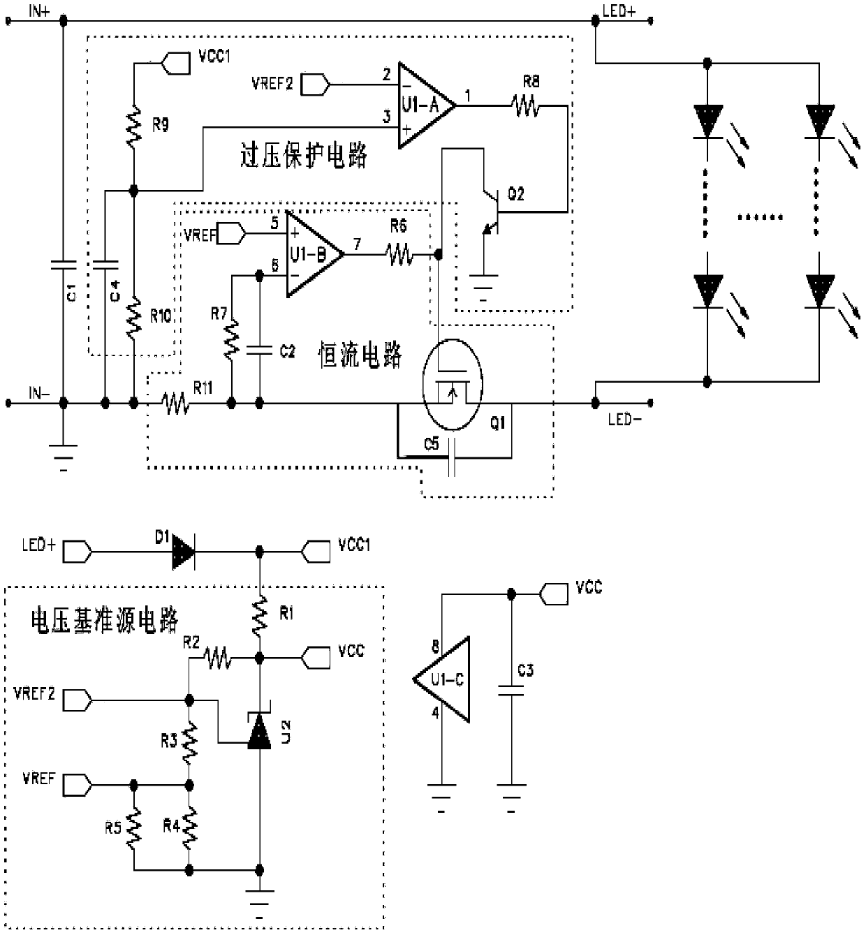
[0018] Such as figure 1 As shown, the present invention discloses an LED constant current device, which includes a voltage reference source circuit, an overvoltage protection circuit, a constant current circuit, and a diode (D1). The positive and negative poles of the power supply are connected, and the negative pole supplies power to the entire constant current circuit.

[0019] The voltage reference source circuit is used to generate three reference voltages, among which VCC supplies power to the dual operational amplifier chip U1, VREF2 is used for the reference voltage of the overvoltage protection circuit, and VREF is used for the reference voltage of the constant current circuit.

[0020] One reference voltage is used for the working voltage of the dual operational amplifier chip U1, another reference voltage is used for the reference voltage of the overvoltage protection circuit, and the last reference voltage is used for the reference voltage of the constant current ci...


PUM


Abstract

The invention provides an LED constant-current unit comprising a voltage reference source circuit, an overvoltage protection circuit, a constant-current circuit and a dual-OP-AMP (dual operational amplifiers) chip (U1). The constant-current circuit comprises a MOSFET (metal oxide semiconductor field-effect transistor) (Q1). The voltage reference source circuit is used for generating three reference voltages; one reference voltage is used as operating voltage of the dual-OP-AMP circuit (U1), another reference voltage is used as reference voltage of the overvoltage protection circuit, and the remaining reference voltage is used as reference voltage of the constant-current circuit. The overvoltage protection circuit is used for detecting input voltage and the corresponding reference voltage and comparing output high-low levels to control off of the MOSFET (Q1). The constant-current circuit is used for detecting circuit current and the corresponding reference voltage and comparing output high-low levels to adjust output current of the MOSFET (Q1). The LED constant-current unit has the advantages that the circuits are simple, the cost is low, efficiency is high, EMI (electromagnetic interference) is avoided, constant-current precision is high, and temperature drift is small.

Description

technical field [0001] The invention relates to the field of electronic circuits, in particular to an LED constant current device. Background technique [0002] At present, most low-voltage LED constant current circuits on the market are DC-DC conversion circuits, which have the following defects: [0003] 1. Low efficiency: only about 90% when powered at 24V and below; [0004] 2. High cost: The DC-DC conversion circuit is generally composed of control chips, MOSFET tubes, energy storage inductors, EMI components, etc. The circuit is complicated and the cost is high; [0005] 3. EMI problems are prone to occur: DC-DC conversion circuits are prone to EMI problems due to the use of high-frequency switching circuits. Contents of the invention [0006] In order to solve the problems in the prior art, the present invention provides an LED constant current device. [0007] The present invention provides an LED constant current device, which includes a voltage reference sourc...

Claims


Application Information

Patent Timeline
Patent Type & Authority Applications(China)
IPC IPC(8): H05B37/02
Inventor 刘永胜
Owner 深圳市奋勇光电有限公司
Learn More