Strobe device

A stroboscopic and reflective surface technology, applied to lighting devices, components of lighting devices, optics, etc., can solve problems such as inability to illuminate

Inactive Publication Date: 2014-12-17
PANASONIC INTELLECTUAL PROPERTY MANAGEMENT CO LTD
View PDF5 Cites 0 Cited by
  • Summary
  • Abstract
  • Description
  • Claims
  • Application Information

AI Technical Summary

Problems solved by technology

As a result, there is a problem that the existing strobe device 9 cannot irradiate the entire area of ​​the object to be photographed with light of an appropriate amount of light.

Method used


Image

  • Strobe device
  • Strobe device
  • Strobe device

Examples


Embodiment approach

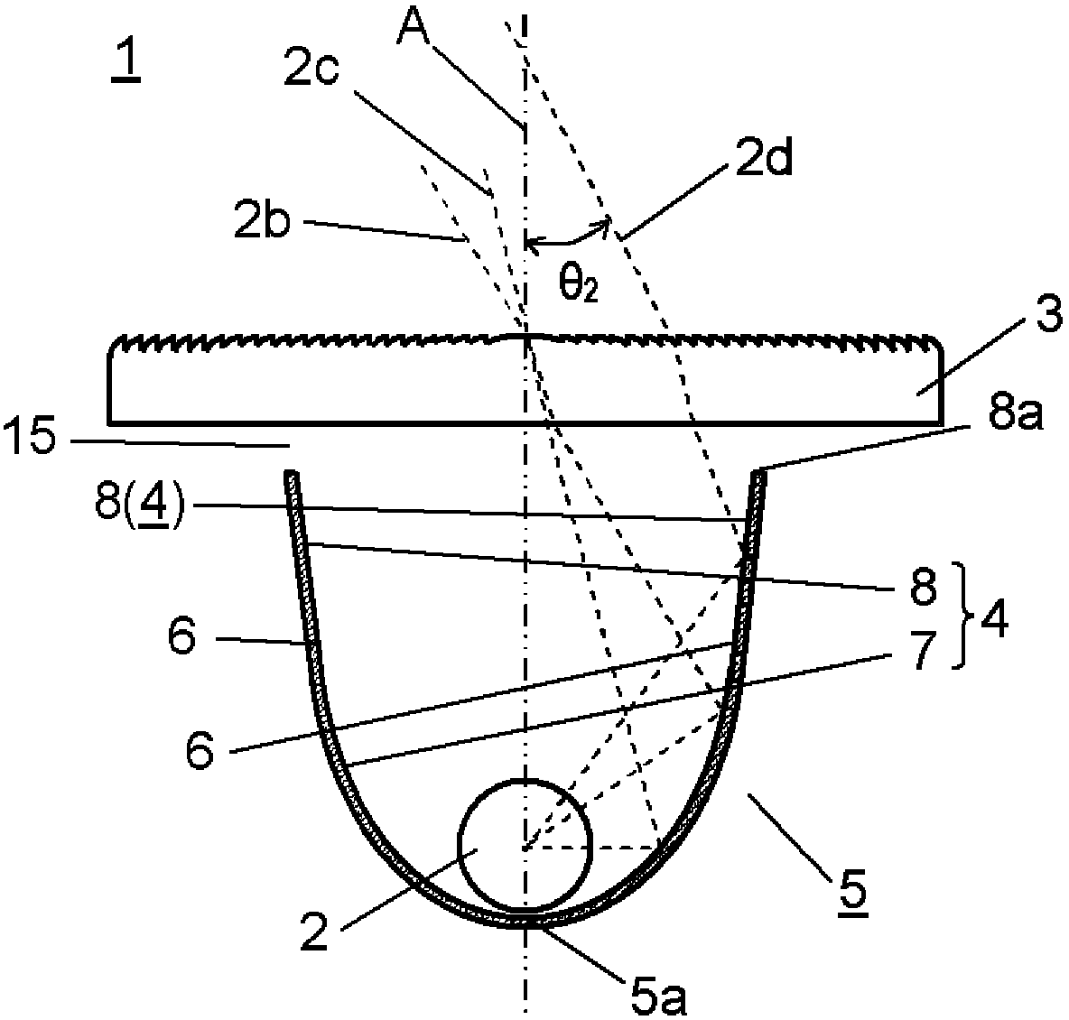
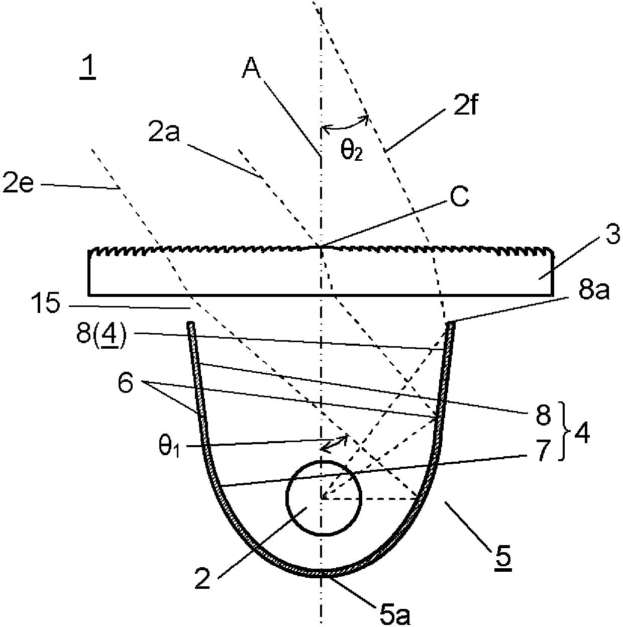
[0024] use Figure 1A and Figure 1B A strobe device according to an embodiment of the present invention will be described.

[0025] like Figure 1A and Figure 1B As shown, the strobe device 1 of the present embodiment at least includes: a light source 2 formed elongated in one direction; an optical member 3 disposed parallel to the longitudinal direction of the light source 2; and a reflector 5 disposed along the light source 2 The longitudinal direction is formed long, and it has the reflection surface 4 which reflects the light from the light source 2 toward the optical member 3. Further, the light source 2 , the optical member 3 , and the reflector 5 are arranged in the direction of the optical axis A along the optical axis A of the strobe device 1 . At this time, as the light source 2, for example, a flash discharge tube such as a flash lamp is used.

[0026] It should be noted that, basically, the strobe device 1 is configured by accommodating the above-mentioned c...


PUM


Abstract

A strobe device is equipped with a light source, an optical member, and a reflector (5) having a reflecting surface (4). The reflecting source (4) is equipped with a first reflecting surface (7) that is formed on the reflector (5) side of a specific reflecting region (6) on the reflecting surface (4), and a second reflecting surface (8) that is formed on the optical member side. Furthermore, the first reflecting surface (7) has a shape which curves such that the center of curvature is on the inside of the reflector (5), and the second reflecting surface (8) has a shape which curves such that the center of curvature is on the outside of the reflector (5) and such that the distance from the light axis center increases as the second reflecting surface approaches the optical member. Accordingly, light from the light source is prevented from radiating outside of a desired region.

Description

technical field [0001] The present invention relates to a strobe device for irradiating light to an area to be imaged. Background technique [0002] Conventionally, for example, a strobe device provided directly or indirectly in imaging equipment such as a digital camera has been disclosed (for example, refer to Patent Document 1). It should be noted that the strobe device irradiates light toward an area to be imaged by the imaging device. [0003] Below, use Figure 4A and Figure 4B The configuration of a conventional strobe device will be described. Figure 4A It is a cross-sectional view showing the structure of a state where a light source is closest to a reflector in a conventional strobe device. Figure 4B It is a cross-sectional view showing the structure of the state where the light source is farthest from the reflector in the conventional strobe device. [0004] like Figure 4A and Figure 4B As shown, the existing strobe device 9 has: a light source 10 formed ...

Claims


Application Information

Patent Timeline
Patent Type & Authority Applications(China)
IPC IPC(8): G03B15/05G03B15/02
CPCG03B15/05G03B2215/0582F21V13/04F21W2111/10
Inventor 吉冈弘幸川端克典
Owner PANASONIC INTELLECTUAL PROPERTY MANAGEMENT CO LTD
Why Eureka
Try Eureka