Back light module unit

A backlight module and back frame technology, applied in light guides, optics, optical components, etc., can solve problems such as bad optical phenomena of backlight modules, achieve the effect of improving display quality and overcoming bad optical phenomena

Inactive Publication Date: 2007-03-07
INNOCOM TECH (SHENZHEN) CO LTD +1
View PDF0 Cites 17 Cited by
  • Summary
  • Abstract
  • Description
  • Claims
  • Application Information

AI Technical Summary

Problems solved by technology

[0008] In order to overcome the problem of bad optical phenomena in the backlight module of the prior art, it is necessary to provide a backlight module that overcomes the bad optical phenomenon and improves the display quality.

Method used


Image

  • Back light module unit
  • Back light module unit
  • Back light module unit

Examples


Embodiment Construction

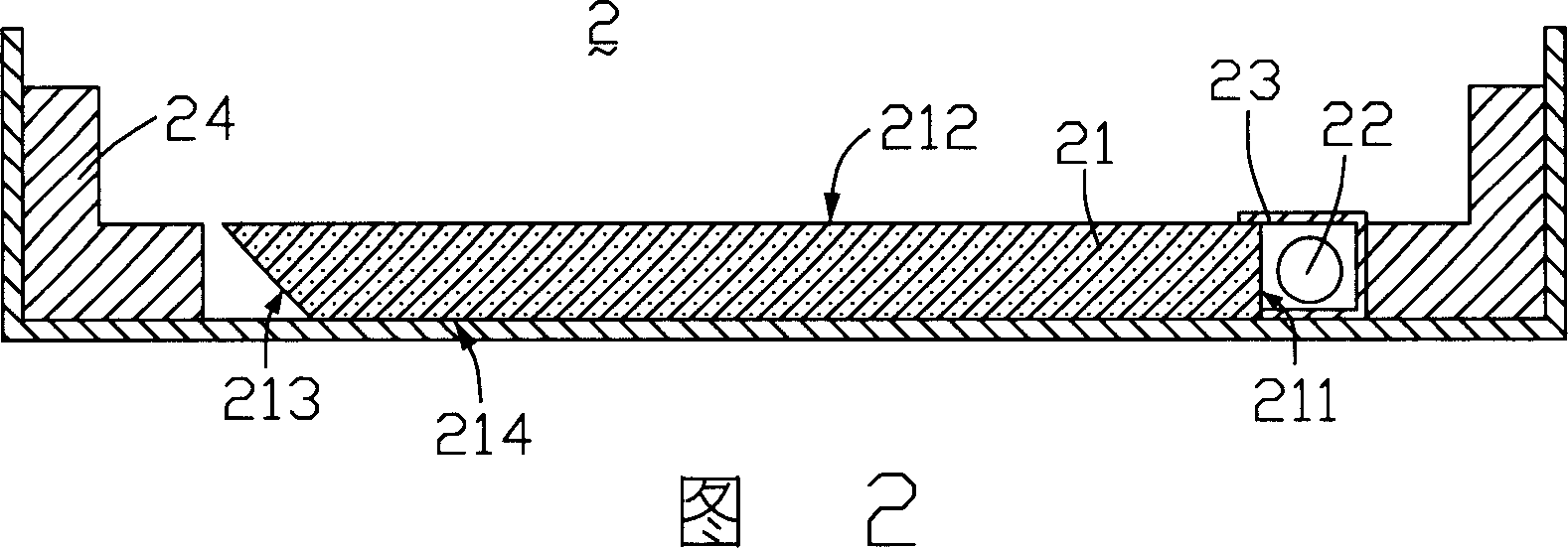
[0018] Please refer to FIG. 2 , which is a schematic cross-sectional view of the first embodiment of the backlight module of the present invention. The backlight module 2 includes a light guide plate 21, a light source 22, a light source cover 23 and a back frame 24, the light source 22 is located on one side of the light guide plate 21, the light source cover 23 is arranged around the light source 22, and the back frame 24 fixes the light guide plate 21 and light source 22 .

[0019] The light guide plate 21 includes a light incident surface 211 for receiving light, a light exit surface 212 intersecting with the light incident surface 211 for guiding the light to exit, a bottom surface 214 opposite to the light exit surface 212, three intersecting the light exit surface and the bottom surface The side surfaces 213 of the light guide plate 21 are inclined.

[0020] The light emitted by the light source 22 enters the light guide plate 21 through the light incident surface 211,...


PUM


Abstract

This invention relates to one aphototropism module set, which comprises one light source, one light board and one back frame, wherein, the frame contains light source and light guide board with one incident surface and one emergent surface to guide the light crossing with incident surface and one bottom surface relative to the emergent surface and the side surface crossing with the emergent surface; the light source is in one side of the incident surface; the guide board side and its relative back frame side has anti-leakage structure to prevent leakage phenomena from the gap between the side surface and back frame.

Description

【Technical field】 [0001] The invention relates to a backlight module, in particular to an edge-light backlight module. 【Background technique】 [0002] Since the liquid crystal in the liquid crystal display panel does not emit light itself, in order to achieve the display effect, it is necessary to provide the liquid crystal display panel with a light source device, such as a backlight module, to realize the display function. [0003] The prior art backlight module includes a light source and a light guide plate. The light source is arranged relative to the light incident surface of the light guide plate. The light guide plate guides the transmission direction of the light emitted by the light source and converts the line light source or point light source into a surface light source to emit. A plurality of dots are distributed on the bottom of the light guide plate to destroy the total reflection condition of light transmission inside the light guide plate, and make it diffu...

Claims


Application Information

Patent Timeline
Patent Type & Authority Applications(China)
IPC IPC(8): G02F1/1335
CPCG02B6/0031G02B6/0016G02B6/002G02F1/133615
Inventor 吕嵩张志弘陈飞虹
Owner INNOCOM TECH (SHENZHEN) CO LTD
Why Eureka
Try Eureka