Light beam scanning device and image forming apparatus

a scanning device and light beam technology, applied in the direction of inking apparatus, printing, instruments, etc., can solve the problems of reducing the number of scanning times (scanning efficiency) per rotation of the polygon mirror b>3/b>, and reducing the printing speed, so as to reduce the size of the apparatus, reduce the distance between the rotary polygon mirror and the imaging optical system, and increase the incidence angle

Active Publication Date: 2006-10-31
BROTHER KOGYO KK
View PDF5 Cites 16 Cited by
  • Summary
  • Abstract
  • Description
  • Claims
  • Application Information

AI Technical Summary

Benefits of technology

[0008]To attain miniaturization, the distance between each of the imaging optical systems 4 and 5 and the polygon mirror 3 must be reduced for this reason. However, as the distance between each of the imaging optical systems 4 and 5 and the polygon mirror 3 decreases, the incidence angle α of the laser light L on the polygon mirror 3 cannot but increase so that the laser light L can be prevented from striking against an end of the imaging optical system 4.
[0026]According to this configuration, the effective scanning range (used for forming an image) of the light beam in the scanning direction is formed so that the center position of the effective scanning range is displaced along the scanning direction from the optical axis of the imaging optical system. Accordingly, the angle α between the center of luminous flux of the light beam toward the deflection surfaces of the rotary polygon mirror and the optical axis of the imaging optical system can be set to satisfy the relational expression (4π / N)−(W / D)≦|α|<(4π / N)−{(W−β) / D}. That is, while the ghost image can be removed from the effective scanning range, the incidence angle α of the light beam on the deflection surfaces of the rotary polygon mirror can be increased without reduction in the number of the deflection surfaces of the rotary polygon mirror, compared with the configuration of Patent Document 1. Because the incidence angle α can be increased, the distance between the rotary polygon mirror and the imaging optical system can be reduced so that the size of the apparatus can be reduced.

Problems solved by technology

Because the number of scanning times (scanning efficiency) per rotation of the polygon mirror 3 is however reduced if the number N of deflection surfaces of the polygon mirror 3 is reduced, there arises a problem that printing speed is lowered unless the polygon mirror 3 is rotated at a higher speed.

Method used


Image

  • Light beam scanning device and image forming apparatus
  • Light beam scanning device and image forming apparatus
  • Light beam scanning device and image forming apparatus

Examples


embodiment 1

[0036 of the invention will be described with reference to FIGS. 1 to 5.

1. Overall Configuration of Laser Printer

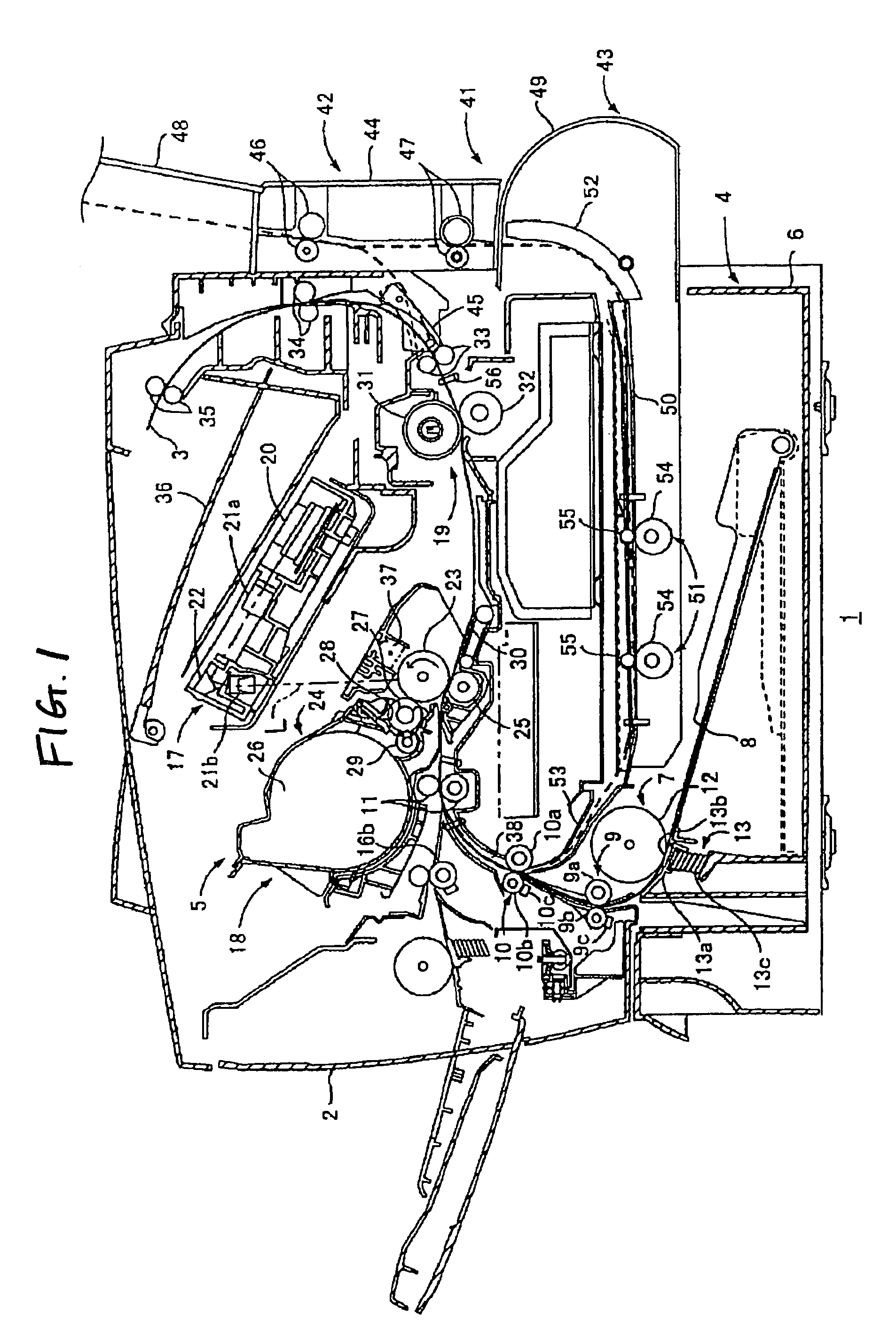
[0037]FIG. 1 is a side sectional view of important part showing the configuration of a laser printer 1 as an image-forming apparatus according to the invention. The laser printer 1 according to this embodiment is provided for forming an image by electrophotography. The laser printer 1 has a body casing 2. A feeder portion 4 for feeding a sheet of paper 3 as a recording medium, an image-forming portion 5 for forming a predetermined image on the fed sheet of paper 3, and so on, are provided in the body casing 2.

(1) Feeder Portion

[0038]The feeder portion 4 has a paper supply tray 6 detachably attached to a bottom portion in the body casing 2, a paper supply mechanism portion 7 provided in a one-end side end portion of the paper supply tray 6, a paper pressing plate 8 provided in the paper supply tray 6, first and second conveyance portions 9 and 10 (which will be described l...


PUM


Abstract

An effective scanning range of laser light in a scanning direction is configured so that a center position of the effective scanning range is displaced by a distance β along the scanning direction from an optical axis f an fθ lens. The incidence angle α between a center of luminous flux of the laser light on a deflection surface of polygon mirror and the optical axis of the fθ lens can beset to satisfy a relational expression (4π / N)−(W / D)≦|α|<(4π / N)−{(W−β) / D}.

Description

BACKGROUND OF THE INVENTION[0001]1. Field of the Invention[0002]The present invention relates to an image-forming apparatus and a light beam scanning apparatus.[0003]2. Description of the Related Art[0004]For example, a laser scanning apparatus (equivalent to a light beam scanning apparatus) provided in a laser printer as an image-forming apparatus has such a configuration as shown in FIG. 8. That is, laser light L (represented by the solid-line arrow in FIG. 8) emitted from a laser light source 1 passes through a cylindrical lens 2 so as to be incident on a deflection surface 3a of a polygon mirror 3. The laser light L reflected on the deflection surface 3a is converged by imaging optical systems 4 and 5 so that an imaging spot Ps is formed on a photosensitive drum surface 6 as an image carrier. The imaging spot Ps is scanned on the photosensitive drum surface 6 as the polygon mirror 3 rotates.[0005]The laser light L incident on the photosensitive drum surface 6 is scattered and re...

Claims


Application Information

Patent Timeline
Patent Type & Authority Patents(United States)
IPC IPC(8): G02B26/08B41J27/00B41J2/44B41J2/47G02B26/10G02B26/12
CPCB41J2/471G02B26/125G02B26/127
Inventor FUJINO, HITOSHI
Owner BROTHER KOGYO KK
Why Eureka
Try Eureka