Pellicle for use in a microlithographic exposure apparatus

a microlithographic and exposure apparatus technology, applied in the field of optical pellicles, can solve the problems of reducing affecting the quality of the image, and affecting the production efficiency of the component, so as to reduce the overall running cost of the projection exposure apparatus, reduce the overall running cost, and reduce the effect of li

Inactive Publication Date: 2009-03-05
CARL ZEISS SMT GMBH
View PDF14 Cites 16 Cited by
  • Summary
  • Abstract
  • Description
  • Claims
  • Application Information

AI Technical Summary

Benefits of technology

[0031]Consequently, there is no need for an additional absorptive filter in a pupil plane that may compensate for the dependency of the transmittance of the pellicle on the angle of incidence.
[0032]Having a transmittance that is almost independent of the angle of incidence over the required range of angles is often the favorable solution in view of imaging properties. However, the application of a plurality of thin layers on one or preferably on both sides of the membrane may involve a complicated and costly manufacturing process. Since pellicles have a restricted life time due to material degradations, costly pellicles may considerably increase the overall running costs of the projection exposure apparatus.

Problems solved by technology

As a result, these particles can produce defects in the component to be produced.
However, it has been discovered that using conventional pellicles in projection exposure apparatuses having an image side numerical aperture beyond 1 results in a degradation of the image quality.

Method used


Image

  • Pellicle for use in a microlithographic exposure apparatus
  • Pellicle for use in a microlithographic exposure apparatus
  • Pellicle for use in a microlithographic exposure apparatus

Examples


Embodiment Construction

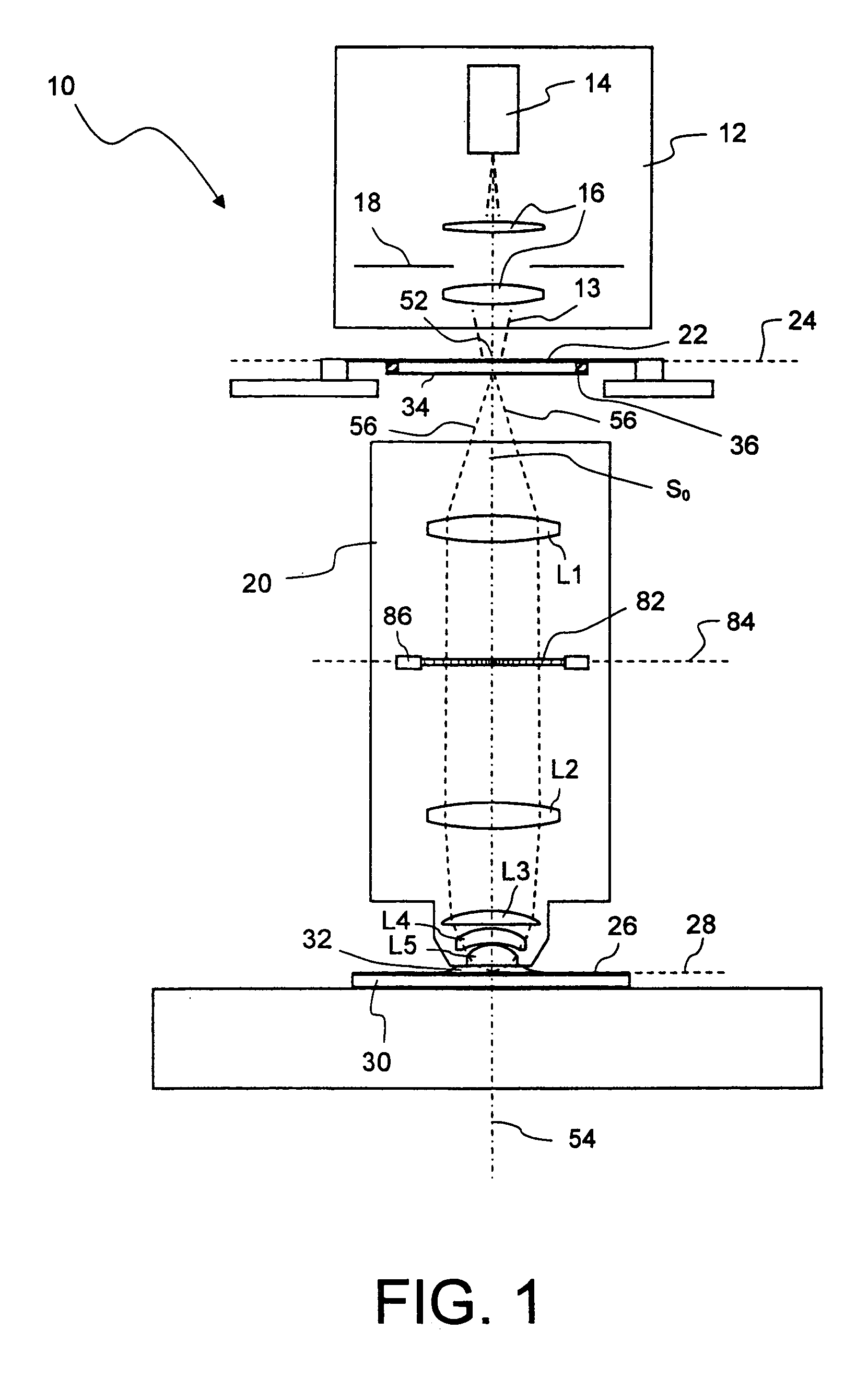
[0044]FIG. 1 shows a meridional section through a microlithographic projection exposure apparatus in a highly simplified representation. The projection exposure apparatus, which is denoted in its entirety by 10, includes an illumination system 12 for generating projection light 13. The illumination system 12 has a light source 14, illumination optics indicated by 16 and a diaphragm 18. In the exemplary embodiment, the projection light has a wavelength of 193 nm. Of course, other wavelengths such as 157 nm or 248 nm, are contemplated as well.

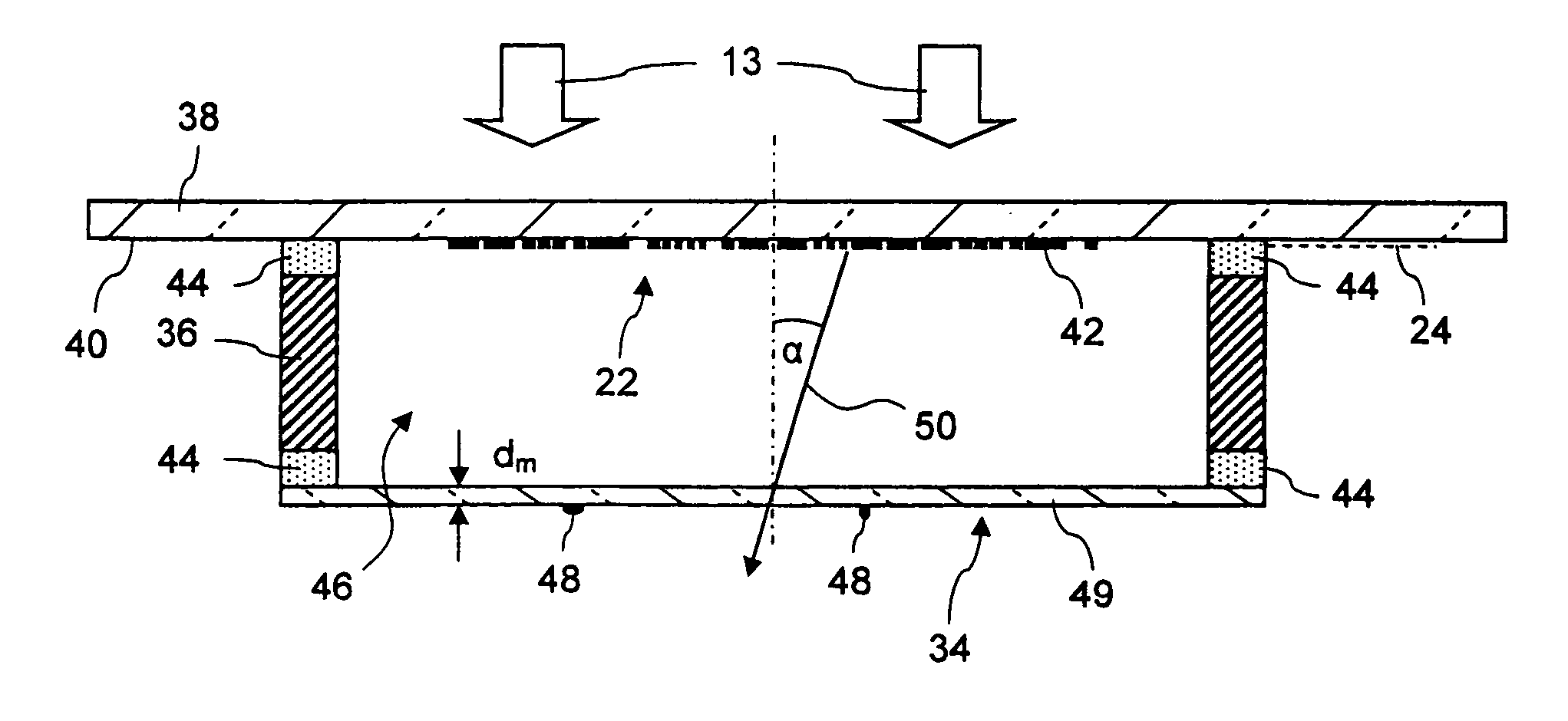
[0045]The projection exposure apparatus 10 further includes a projection lens 20 containing a multiplicity of lens elements. For the sake of simplicity, only very few lens elements L1 to L5 are schematically indicated in FIG. 1. The projection lens 20 is used to image a mask 22 arranged in an object plane 24 of the projection lens 20 on a photoresist 26. In this embodiment the projection lens 20 has a magnification M=¼ so that the pattern formed ...


PUM


Abstract

A pellicle for use in microlithographic exposure apparatus (10) has, for an operating wavelength of the apparatus, a maximum transmittance for light rays (56) that obliquely impinge on the pellicle (34; 134; 234). This ensures smaller variations of the transmittance over a broad range of angles of incidence, as it occurs in very high numerical aperture projection lenses.

Description

BACKGROUND OF THE INVENTION[0001]1. Field of the Invention[0002]The present invention relates to optical pellicles for preventing adhesion of dust or other particles to a mask used in a microlithographic exposure apparatus.[0003]2. Description of Related Art[0004]Microlithography, which is also referred to as photolithography, is a technology for the fabrication of integrated circuits, liquid crystal displays and other microstructured devices. More particularly, the process of microlithography, in conjunction with the process of etching, is used to pattern features in thin film stacks that have been formed on a substrate, for example a silicon wafer. At each layer of the fabrication, the wafer is first coated with a photoresist or another material that is sensitive to radiation, for example deep ultraviolet (DUV) light. Next, the wafer covered with the photoresist is exposed to projection light through a mask in a projection exposure apparatus. Amplitude masks contain a pattern of o...

Claims


Application Information

Patent Timeline
Patent Type & Authority Applications(United States)
IPC IPC(8): G03B27/52F21V9/06G03B27/72
CPCG03F1/62G03F7/70341G03F7/70308G03F1/46G03F7/70283G03F7/7055H01L21/0276
Inventor GOEHNERMEIER, AKSELPAZIDIS, ALEXANDRA
Owner CARL ZEISS SMT GMBH
Why Eureka
Try Eureka