Mechanism for mixing nitrogen fertilizer and phosphorus in ratio and applying mixed fertilizer

A technology of proportional mixing and fertilizing mechanism, applied in the field of agricultural machinery research, can solve the problems of unstable operation quality, increased resistance of equipment, unstable center of gravity, etc., to save manpower and energy, reduce ditching resistance, and improve operation. quality effect

Inactive Publication Date: 2014-12-24
NORTHWEST A & F UNIV
View PDF6 Cites 6 Cited by
  • Summary
  • Abstract
  • Description
  • Claims
  • Application Information

AI Technical Summary

Problems solved by technology

If nitrogen and phosphorus fertilizers are mixed in the same fertilizer tank, nitrogen and phosphorus fertilizers will be layered up and down due to the different densities of nitrogen and phosphorus fertilizers, making the nitrogen and phosphorus fertilizers fertilized unevenly, and the dense phosphorus fertilizers are discharged first, followed by nitrogen fertilizers; Nitrogen and phosphate fertilizers are placed in two different fertilizer boxes, and two sets of ditching and fertilization mechanisms are required. The resistance of the machine tool increases, and a large-power tractor is required. The front and rear geometric dimensions of the machine tool become larger, and the center of gravity is behind, which is not conducive to the machine tool. Improve unloaded driving
These three fertilization mechanisms and methods cannot well meet the needs of nitrogen and phosphorus fertilization when crops are planted.
Applying two kinds of fertilizers in a single fertilizer box requires machines to enter the ground twice, and the production cost is high; nitrogen and phosphorus fertilizers are mixed in the same fertilizer box, fertilization is uneven, and the operation quality is unstable; double fertilizer boxes are independently discharged, and the fertilization mechanism is complicated and the resistance is large. And the center of gravity is unstable

Method used


Image

  • Mechanism for mixing nitrogen fertilizer and phosphorus in ratio and applying mixed fertilizer
  • Mechanism for mixing nitrogen fertilizer and phosphorus in ratio and applying mixed fertilizer

Examples


Embodiment Construction

[0015] Below in conjunction with accompanying drawing, the present invention will be further described:

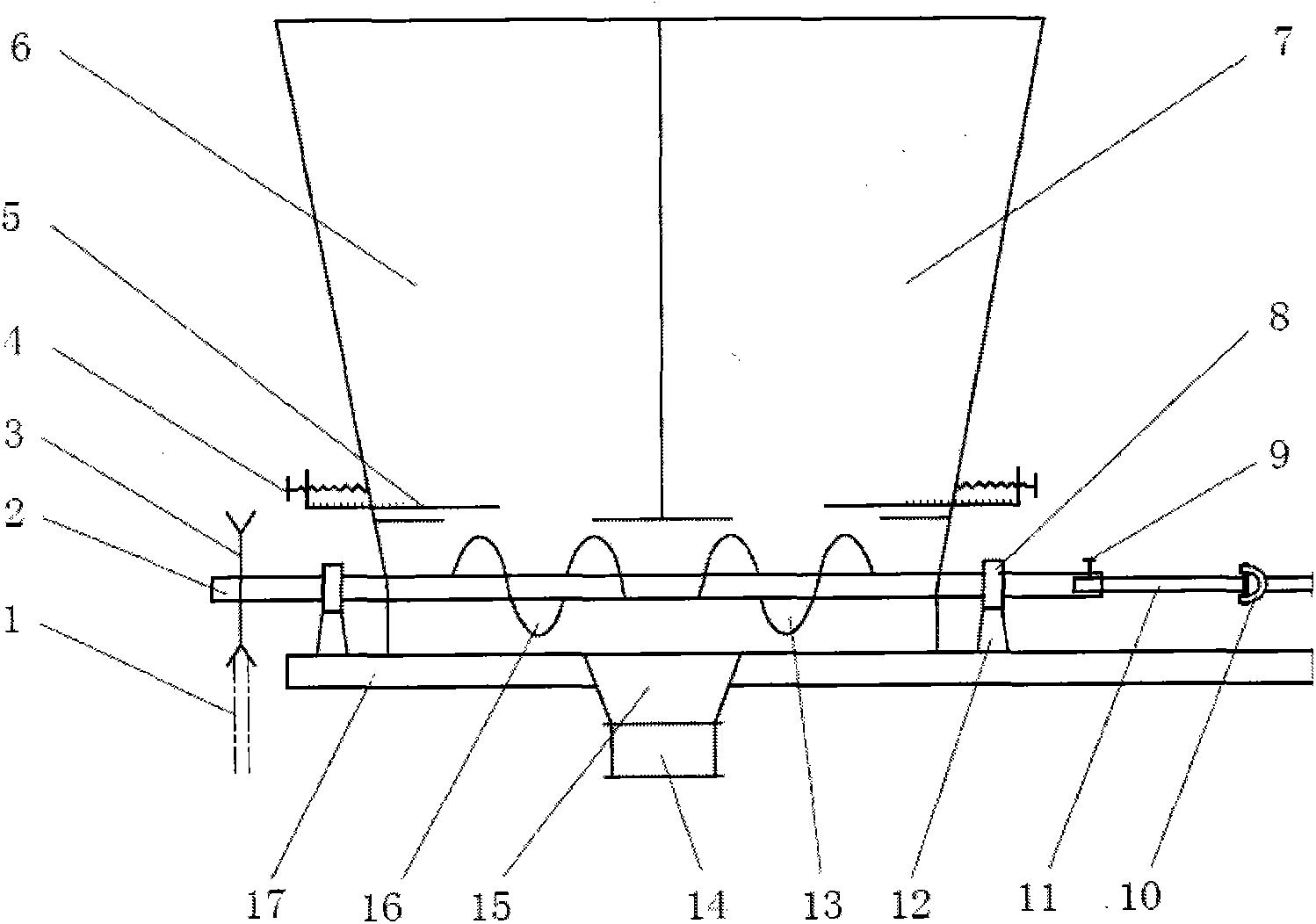
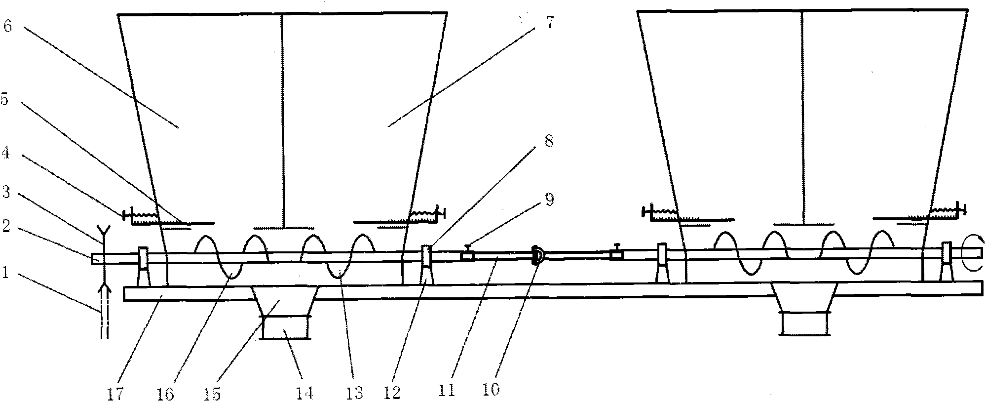
[0016] figure 1 It is a schematic diagram of a nitrogen-phosphorus fertilizer ratio mixed fertilizer discharge mechanism of the present invention, including a frame 17, a main shaft 2, a nitrogen fertilizer box 6, a phosphate fertilizer box 7, a left-handed screw 13, a right-handed screw 16, a fertilizer control panel 5, and a mixed fertilizer pipe Joint 14, the main shaft 2 is installed on the frame 17 through the bearing 8 and the bearing block 12, the nitrogen fertilizer box 6 and the phosphate fertilizer box 7 are fixedly installed on the frame 17, and the left-handed helix 13 and the right-handed helix 16 are welded and fixed On the main shaft 2, the collector 15 and the mixed fertilizer pipe joint are installed below the frame 17;

[0017] Sprocket wheel 3 is installed on described main shaft 2, and fertilizer amount control board 5 and adjusting screw 4 are install...


PUM


Abstract

The invention discloses a mechanism for mixing nitrogen fertilizer and phosphorus fertilizer in a ratio and applying mixed fertilizer. The mechanism comprises a rack, a spindle, a left spiral, a right spiral, a nitrogen fertilizer box, a phosphorus fertilizer box, a fertilizer quantity control device, a collector and a mixed fertilizer tube joint, wherein the spindle, the nitrogen fertilizer box and the phosphorus fertilizer box are arranged on the upper part of the rack; the left spiral and the right spiral are fixed on the spindle; the fertilizer quantity control device is arranged at the bottom of the nitrogen fertilizer box and the phosphorus fertilizer box; the collector and the mixed fertilizer tube joint are arranged on the lower part of the rack. According to the mechanism, the nitrogen fertilizer and the phosphorus fertilizer can be mixed according to a ratio and then the mixed fertilizer is applied. The mechanism has the beneficial effects that the fertilizers are uniformly mixed, energy is saved, the operating efficiency is high, and the fertilization quality is stable.

Description

technical field [0001] The invention relates to a nitrogen-phosphorus fertilizer ratio mixed fertilizer discharge mechanism, in particular to the research field of agricultural machinery suitable for fertilizing when sowing dry wheat. Background technique [0002] The fertilizer discharge mechanism of the existing wheat fertilization seeder is a fertilizer discharge wheel, which can only discharge one kind of fertilizer, such as nitrogen fertilizer or phosphorus fertilizer. If nitrogen and phosphorus fertilizers are mixed in the same fertilizer tank, nitrogen and phosphorus fertilizers will be layered up and down due to the different densities of nitrogen and phosphorus fertilizers, making the nitrogen and phosphorus fertilizers fertilized unevenly, and the dense phosphorus fertilizers are discharged first, followed by nitrogen fertilizers; Nitrogen and phosphate fertilizers are placed in two different fertilizer boxes, and two sets of ditching and fertilization mechanisms a...

Claims


Application Information

Patent Timeline
Patent Type & Authority Applications(China)
IPC IPC(8): A01C7/06A01C15/00
Inventor 王朝辉朱琳刘金山
Owner NORTHWEST A & F UNIV
Why Eureka
Try Eureka