Plastic impeller for impeller aerator

An impeller aerator and impeller technology, applied in applications, mechanical equipment, machines/engines, etc., can solve the problems of not being able to achieve oxygen aeration, water cultivation, surge, optional blades, and single form at the same time, so as to facilitate water breaking. Easy to install and move, easy to produce

Active Publication Date: 2015-12-30
金湖小青青机电设备有限公司
View PDF8 Cites 0 Cited by
  • Summary
  • Abstract
  • Description
  • Claims
  • Application Information

AI Technical Summary

Problems solved by technology

[0003] The technical problem to be solved by the present invention is to provide a plastic impeller for an impeller aerator. This invention not only effectively solves the problem that the traditional plastic impeller has a single form and cannot simultaneously realize the functions of increasing oxygen, cultivating water, and surging waves, but also effectively solves the problem of The problem that the traditional impeller is integrally injection-molded, and it is impossible to choose blades according to the needs of oxygenation

Method used


Image

  • Plastic impeller for impeller aerator
  • Plastic impeller for impeller aerator
  • Plastic impeller for impeller aerator

Examples


Embodiment 1

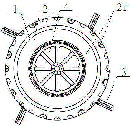
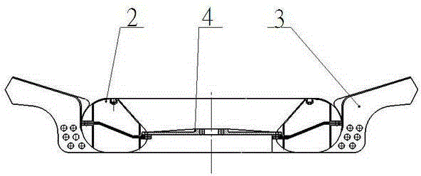
[0030] Such as figure 1 , 2 As shown in . The flange is fixedly connected with the drive shaft of the motor. The sealing floating body 2 is made by integral blow molding process and is an integral hollow ring body. The outer and inner edges of the sealing floating body 2 are provided with a plurality of mounting holes 21. The sealing floating body 2 The mounting hole 21 provided on the outer edge is provided with blades 3, the sealing floating body 2 is provided with a connecting support plate 4 through the mounting hole 21 provided on the inner edge, and the bottom of the sealing floating body 2 is evenly provided with a plurality of limiting grooves 22 along the radial direction, The limit groove 22 is narrower and narrower radially toward the outer edge opening, and is tapered; the connecting support plate 4 is made by injection molding process, including an annular disc 41, a circular disc 43, an annular disc 41 and a circular disc. The discs 43 are fixed into a whole by...

Embodiment 2

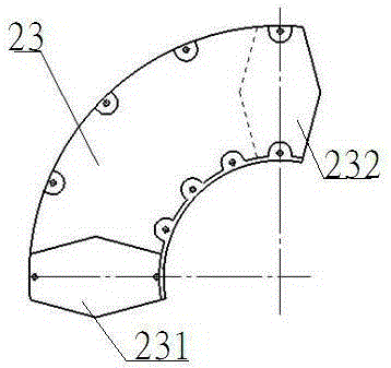
[0032] Such as figure 1 , 2, 3, 4, 5, and 6, the present invention includes an impeller body 1, the impeller body 1 includes a sealing floating body 2, the sealing floating body 2 is provided with blades 3 along the circumferential direction, and the central position of the sealing floating body 2 is provided with a connecting support plate 4, connected The support plate 4 is fixedly connected with the motor drive shaft through the flange, and the sealing floating body 2 is made by blow molding technology, and is composed of a plurality of arc sealing monomers 23, and one end of the arc sealing monomer 23 is a convex connection part 231 , the opposite end is a concave connection part 232, and the adjacent arc sealing monomers 23 are fixedly connected by a convex connection part 231 and a concave connection part 232, and the outer edge and inner edge of the sealing floating body 2 are provided with a plurality of installation holes 21. The sealing floating body 2 is provided w...


PUM


Abstract

The invention discloses a plastic impeller used for an impeller aerator. The plastic impeller used for the impeller aerator comprises an impeller body (1), wherein the impeller body (1) comprises a sealing floating body (2); the sealing floating body (2) is provided with vanes (3) along the circumstance; the middle part of the sealing floating body (2) is provided with a connecting supporting plate (4); the connecting supporting plate (4) is fixedly connected with a motor driving shaft by a flange. The plastic impeller used for the impeller aerator is characterized in that the sealing floating body (2), the connecting supporting plate (4) and the vanes (3) are all manufactured by injection molding technology. According to the plastic impeller used for the impeller aerator, the problem that functions of oxygenation, water culture and surge can not be simultaneously realized since a traditional plastic impeller has a single form can be effectively solved, and the problem that the vanes cannot be selected for the traditional impeller according to oxygenation requirements since the traditional impeller is integrally injected can be effectively solved.

Description

technical field [0001] The invention relates to the technical field of aquaculture aeration equipment, in particular to a plastic impeller for an impeller aeration machine. Background technique [0002] With the continuous development of my country's aquaculture industry and the continuous improvement of consumers' purchasing power of fish food, the contradiction between supply and demand continues to increase. At this time, it is necessary to breed more seedlings in ponds with a fixed area. Oxygen-increasing pumps have become an indispensable oxygen-increasing equipment for existing aquaculture. Aerators are important equipment for aquaculture in my country, and impeller-type aerators are the most widely used in various aerators. The impeller of the impeller type aerator is the key component of the aerator. At present, the impeller of the traditional impeller aerator mainly includes iron impeller and plastic impeller. The existing plastic impeller is light in weight, corrosio...

Claims


Application Information

Patent Timeline
Patent Type & Authority Patents(China)
IPC IPC(8): A01K63/04F04D29/02F04D29/22F04D29/24
Inventor 张晓青赵建宝于亚洲李成雨
Owner 金湖小青青机电设备有限公司
Why Eureka
Try Eureka