
Bead stringing machine with manipulators and operating method of bead stringing machine

A technology of manipulator and bead threading machine, which is applied in the field of bead threading machine, can solve the problems of lower product qualification rate, low processing efficiency, and bead cracking, so as to improve product quality and product qualification rate, reduce labor intensity, and avoid human errors. Effect

Inactive Publication Date: 2014-12-24
ZHONGSHAN JUCHANG AUTOMATION EQUIP TECH CO LTD
View PDF10 Cites 2 Cited by
  • Summary
  • Abstract
  • Description
  • Claims
  • Application Information

AI Technical Summary

Problems solved by technology

The market demand for stringed beads is very large, but the process of threading beads is very troublesome. The existing beading operations are basically artificial, which not only reduces the processing efficiency, but also cannot continue to work for a long time; while the beading operation Due to human error, the processing quality cannot be guaranteed; there are also some bead threading machines on the market, but these bead threading machines basically use gravity to make the side of the beads with the through hole uniformly oriented through vibration, and then enter the threading machine. In the bead thread, because the bead thread is very soft, it needs a rather complicated structure to fix it on the bead threader and let the beads be penetrated. In addition to the complex structure of this bead threader, the most important thing is , the beads are very easy to collide with the parts on the equipment, resulting in collision damage, cracking or missing a corner of the beads, resulting in a decline in product quality and a reduction in the pass rate of the product

Method used


Image

  • Bead stringing machine with manipulators and operating method of bead stringing machine
  • Bead stringing machine with manipulators and operating method of bead stringing machine
  • Bead stringing machine with manipulators and operating method of bead stringing machine

Examples


Embodiment Construction

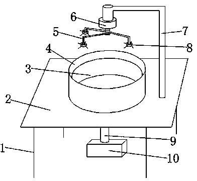
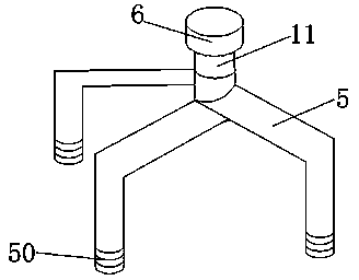
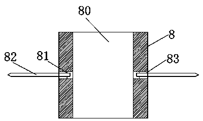
[0020] refer to Figure 1 to Figure 3 As shown, a bead threading machine with a manipulator includes a bracket 1, a support platform 2 arranged above the bracket 1, a fixed disk 4 arranged above the support platform 2, and a rotating disk 3 arranged in the fixed disk 4 , and the support column 7 that is arranged on the right side of the fixed plate 4, and the fixed block 6 that is arranged on the end of the support column 7, and the telescopic rod 11 that is arranged below the fixed block 6, and the manipulator 5 that is arranged on the telescopic rod 11, And the fixed rod plate 8 that is arranged on the end of the manipulator 5, and the main shaft 9 that runs through the support table 2, and the motor 10 that is arranged below the main shaft 9; the end of the manipulator 5 is provided with a thread 50; the fixed rod disc 8 It includes a fixed rod wall 84, a first through hole 80 located in the middle of the fixed rod wall 84, a second through hole 83 passing through the fixed...


PUM


Abstract

The invention discloses a bead stringing machine with manipulators. The bead stringing machine comprises a bracket, a supporting table above the bracket, a fixed disk above the supporting table, a rotating disk in the fixed disk, a supporting column on the right side of the fixed disk, a fixed block at the end part of the supporting column, a telescopic rod below the fixed block, manipulators on the telescopic rod, fixed rod disks at the end parts of the manipulators, a main shaft penetrating through the supporting table and a motor below the main shaft, wherein threads are formed at the end parts of the manipulators; the fixed rod disks comprise fixed rod walls, first through holes formed in the middle parts of the fixed rod walls, second through holes running through the fixed rod walls, buckles positioned in the second through holes and bead stringing rods; one end of each bead stringing rod is positioned in the corresponding second through hole; a threading hole is formed in one end of each bead stringing rod; the other end of each bead stringing rod is of a rhombic structure; wires are arranged between the motor and the manipulators. The bead stringing machine with the manipulators has the advantages of high product quality, high product yield, low labor intensity and high processing quality, and can operate continuously.

Description

technical field [0001] The invention relates to a bead threading machine with a manipulator and a working method thereof. Background technique [0002] As the appearance embellishment and daily necessities of many articles, beads cannot be taken directly, and certain processing is required, especially the need to drill holes on the beads and then thread the beads into strings. The market demand for stringed beads is very large, but the process of threading beads is very troublesome. The existing beading operations are basically artificial, which not only reduces the processing efficiency, but also cannot continue to work for a long time; while the beading operation Due to human error, the processing quality cannot be guaranteed; there are also some bead threading machines on the market, but these bead threading machines basically use gravity to make the side of the beads with the through hole uniformly oriented through vibration, and then enter the threading machine. In the...

Claims


Application Information

Patent Timeline
Patent Type & Authority Applications(China)
IPC IPC(8): A44C27/00
Inventor 王毅陈旭俊王定戒
Owner ZHONGSHAN JUCHANG AUTOMATION EQUIP TECH CO LTD
Learn More