Filtering device at wellhead of water injection well in exploitation of low-permeability oil field

A filter device and water injection well technology, which is applied in the direction of filtration and separation, mining fluid, wellbore/well components, etc., can solve the problems of affecting the filtering effect, easy damage of the winding wire of the filter screen, secondary pollution, etc., and achieve the working life cycle Long-term, prolong service life, reduce corrosion and oxidation effect

Inactive Publication Date: 2014-12-24
SHANGHAI JINGTENG TECH
View PDF5 Cites 3 Cited by
  • Summary
  • Abstract
  • Description
  • Claims
  • Application Information

AI Technical Summary

Problems solved by technology

In addition, the injected water has to be transported through long-distance pipelines from sewage treatment to water injection wells, which will cause secondary pollution
The filter device of the prior art still has the following problems: 1. The screen tubes of the filter pipes currently used mostly adopt the circular pipe split and fish scale hole structure, and the flow area of ​​the round pipe split is about 10%, and the sand particles It is easy to get stuck in the gap and affect the filtering effect; the flow area of ​​the fish scale pore structure is 30%, and the sand particles are also easy to get stuck in the gap
2. The pressure bearing capacity of the filter tube is limited, and the winding wire of the filter screen is easily damaged and replaced frequently; 3. During the transportation process, the filter screen is easily corroded and oxidized; 4. The filter screen is inconvenient to clean

Method used


Image

  • Filtering device at wellhead of water injection well in exploitation of low-permeability oil field

Examples


Embodiment Construction

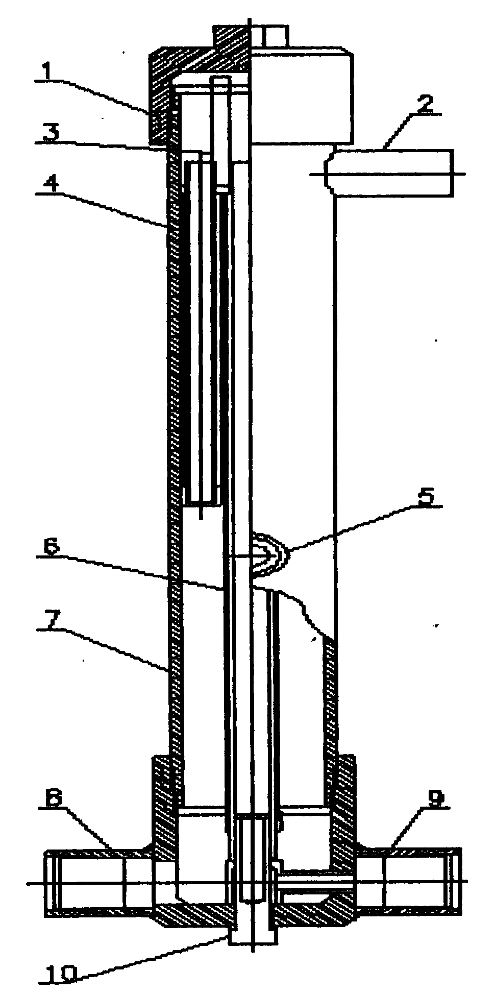
[0017] The structural features of the present invention are further described below in conjunction with the drawings and specific embodiments.

[0018] Such as figure 1 As shown, a wellhead filter device for water injection wells in low-permeability oilfield exploitation includes a filter tube body 7. The upper end of the tube body 7 is closed with a tube body upper cap 1, and the central axis of the tube body 7 runs through a central tube up and down, and the outer side of the central tube The main filter tube 6 is provided, and the inner side of the tube body 7 is provided with four sets of auxiliary filter tubes 4; the middle side wall of the tube body 7 is provided with a liquid inlet 5, and the upper side wall of the tube body 7 is provided with an oil pipe water injection port 2, and the tube body 7 The bottom side wall is provided with a casing water injection port 9 and a sewage outlet 8; the oil pipe water injection port 2 and the casing water injection port 9 are commun...


PUM


Abstract

The invention discloses a filtering device at a wellhead of a water injection well in exploitation of a low-permeability oil field. The filtering device comprises a filter pipe body, wherein the upper end of the pipe body is closed by an upper cap of the pipe body; a central pipe penetrates through the central axis of the pipe body from top to bottom; the outer side of the central pipe is provided with a main filtering pipe; the inner side of the pipe body is provided with four groups of auxiliary filtering pipes; a liquid inlet is formed in the side wall of the middle part of the pipe body; an oil-pipe water filling port is formed in the side wall of the upper part of the pipe body; and a sleeve water filling port and a sewage discharging port are formed in the side wall of the bottom part of the pipe body. The filtering device disclosed by the invention has the beneficial effects that due to the application of trapezoidal or wedge-shaped wire winding of the filtering pipes, a V-shaped opening is formed by the gaps among sieving pipes. Compared with other forms, the filtering device adopting the design form has the advantages that the operation efficiency of products is higher, and the smoothness of filtering of water sources is guaranteed; simultaneously, the opening area percentage and the non-blocking type of the sieving pipes are guaranteed, and the blocking caused by high-density stacking of precipitates is avoided, so that guarantee is provided for improving the production efficiency or prolonging the service life of the water well; and due to the addition of electro-chemical anti-corrosion cathode bars, the reduction of the corrosion and the oxidation by the quality of filled water to the filtering pipes is guaranteed.

Description

Technical field [0001] The invention discloses a filtering device, in particular a wellhead filtering device for water injection wells in low-permeability oilfield exploitation. Background technique [0002] Low-permeability oil fields refer to oil fields with low permeability, low abundance and low single well productivity. In the development of low-permeability oil fields, water injection exploitation is still the main oil production method. Low-permeability oil fields have very high requirements for water injection quality, which must be treated before they can be used. In addition, the injected water has to be transported through long-distance pipelines from sewage treatment to water injection wells, which will cause secondary pollution. The prior art filter device still has the following problems: 1. The screens of the currently used filter tubes mostly adopt round pipe slit type and fish scale hole structure, and the flow area of ​​the round pipe slit type is about 10%, a...

Claims


Application Information

Patent Timeline
IPC IPC(8): B01D29/48E21B43/20
Inventor 朱明辉
Owner SHANGHAI JINGTENG TECH
Why Eureka
Try Eureka