Drilling jig for machining connecting gusset of rotating frame of annular cooler and using method

A technology for connecting angle plates and revolving frames, applied in the direction of drilling dies for workpieces, etc., can solve the problems of unreliable guarantee of manufacturing accuracy, low production efficiency, etc., to shorten the time of a large number of auxiliary processes, accurate and reliable positioning, and improve production operations. The effect of efficiency

Active Publication Date: 2014-12-24
HUNAN ZHONGZHI CHANGTIAN HEAVY IND TECH
View PDF5 Cites 3 Cited by
  • Summary
  • Abstract
  • Description
  • Claims
  • Application Information

AI Technical Summary

Problems solved by technology

[0009] The technical problem to be solved by the present invention is the low production efficiency and the unreliable guarantee of the manufacturing precision existing in the processing technology of the connecting angle plate of the rotary frame of the annular cooler

Method used


Image

  • Drilling jig for machining connecting gusset of rotating frame of annular cooler and using method
  • Drilling jig for machining connecting gusset of rotating frame of annular cooler and using method
  • Drilling jig for machining connecting gusset of rotating frame of annular cooler and using method

Examples


Embodiment 1

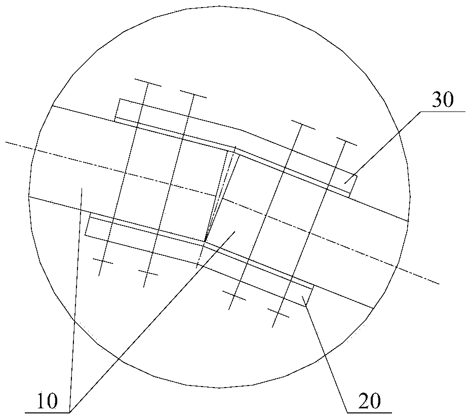
[0043] See Figure 7 with Figure 8 ,in, Figure 7 It is the front view of the drilling jig used to process the connecting angle plate of the rotary frame of the annular cooler described in this embodiment, Figure 8 for Figure 7 top view.

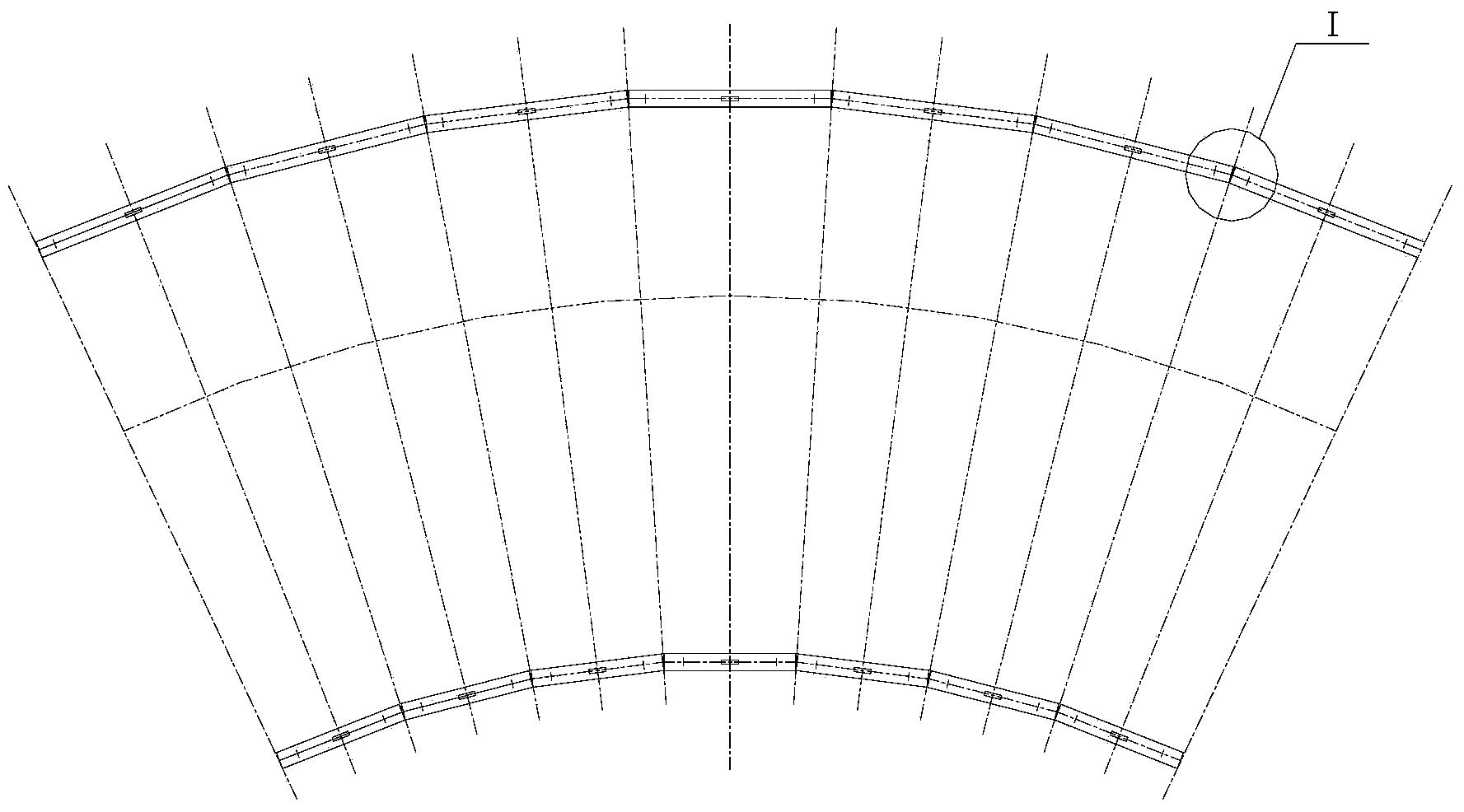
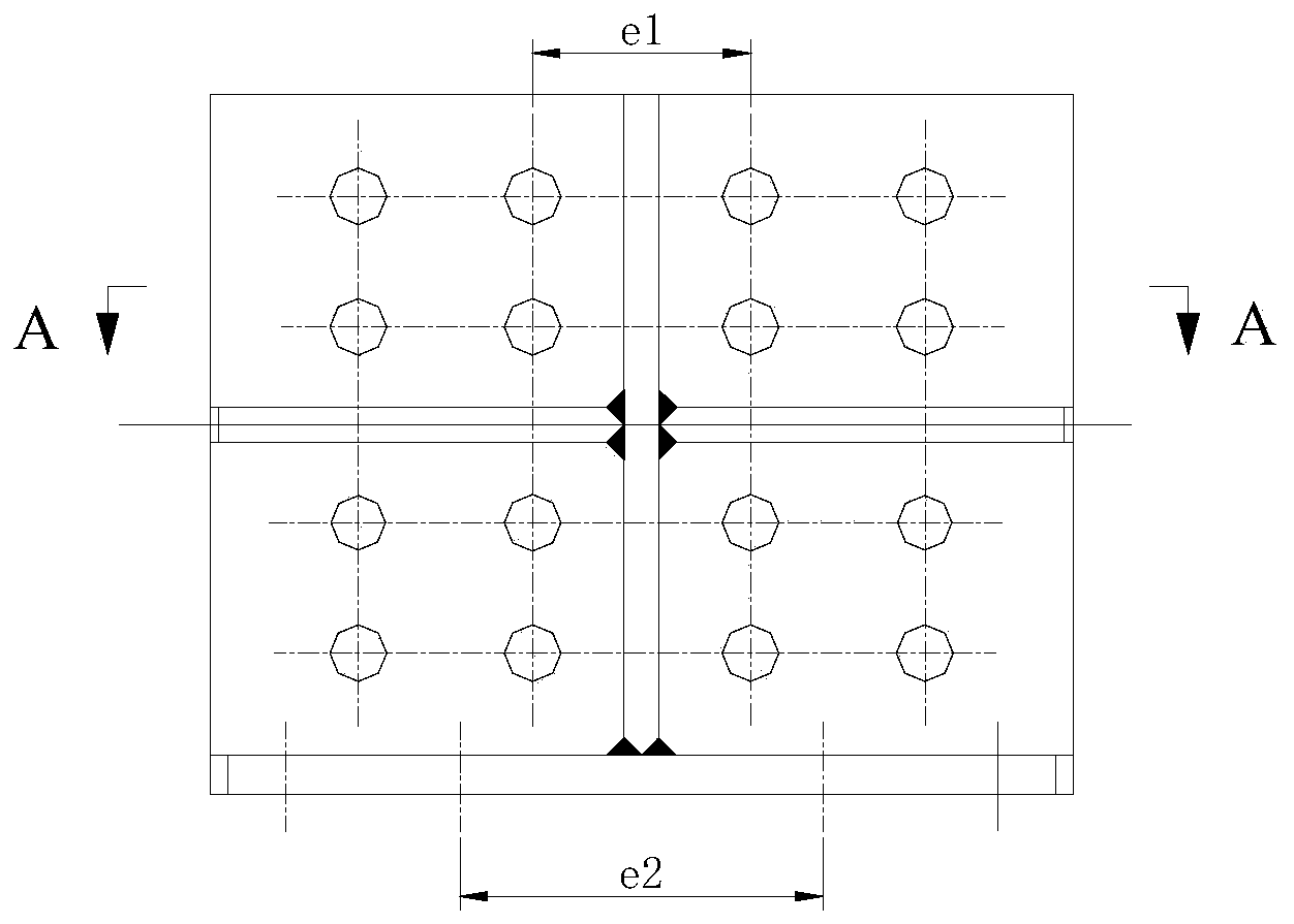
[0044] Based on the feature that the hole spacings L1, L2, L3 and L4 of the connecting holes on the connecting angle plate of the rotary frame of the annular cooler adopt standard design, the present invention provides a corresponding drilling mold. As shown in the figure, the drill template includes two hinged drill template bodies 1, the relative positional relationship between the two drill template bodies can be adjusted, and each drill template body 1 is respectively provided with a working hole connected to the gusset to be processed. Correspondingly, there are a plurality of die holes 11, 12, and the same side of the two drill die bodies 1 is used to bear against the connecting angle plate to be processed, so as to complete the...

Embodiment 2

[0054] This embodiment is the same as the first embodiment in terms of basic composition and connection relationship, the difference lies in that the adjustment mechanism 2 with a different structure is adopted. See Figure 12 , which is a top view of the drilling jig used to process the connecting angle plate of the rotary frame of the annular cooler described in this embodiment. In order to clearly show the difference and connection between this solution and the first embodiment, the same functional components are designated with the same marks generation.

[0055] In this solution, the adjustment mechanism 2 also includes two fixing frames 21, which are respectively arranged on the two drilling template bodies 1, and the two bolts 24 respectively form a threaded matching pair with one of the two fixing frames 21, and each The rod ends of the bolts 24 respectively abut against the other of the two fixing frames 21 to adjust the working angle between the two drilling templat...


PUM


Abstract

The invention relates to the technical field of machining of annular coolers, and provides a drilling jig for machining a connecting gusset of a rotating frame of an annular cooler. The drilling jig comprises two hinged drilling jig bodies and a regulation mechanism, wherein a plurality of jig holes corresponding to working holes of the connecting gusset to be machined are formed in each drilling jig body; the same sides of the two drilling jig bodies are used for supporting and pressing the connecting gusset to be machined; the regulation mechanism is arranged between the two hinged drilling jig bodies to regulate a working angle between the two drilling jig bodies. The drilling jig can be adapted to changes in included angles of connecting gussets of annular coolers in different specifications, and is multipurpose and higher in universality, so that the manufacturing cost of a product is greatly lowered; in addition, the drilling jig has higher operability on a machining site, and a working angle of the drilling jig can be ensured to be adapted to and consistent with the included angle of the connecting gusset to be machined, so that accurate and reliable positioning is ensured. Compared with the prior art, the drilling jig has the advantages that the time of auxiliary procedures in a machining process is greatly shortened, and the production operation efficiency is greatly improved.

Description

technical field [0001] The invention relates to the technical field of processing an annular cooler, in particular to a drilling mold for processing a connecting angle plate of a rotary frame of an annular cooler and a using method thereof. Background technique [0002] The sinter ring cooler (referred to as the ring cooler) is an important host equipment for sinter production in the iron and steel industry. Its core components for circular motion, the trolley and the rotary frame, adopt a regular polygon layout. As we all know, the revolving frame of the whole ring cooler is composed of as many as dozens of revolving frame beams of the same structure to form a full circle of regular polygonal structure. Obviously, how to ensure the regular polygonal position of the revolving frame is the key to ensure the movement and use of the ring cooler. Key technologies for performance. [0003] See figure 1 with figure 2 ,in, figure 1 A schematic diagram of the partial structure ...

Claims


Application Information

Patent Timeline
IPC IPC(8): B23B47/28B23B35/00
CPCB23B35/00B23B47/28
Inventor 曹胜年薛华伟周柏林吴寅生
Owner HUNAN ZHONGZHI CHANGTIAN HEAVY IND TECH
Why Eureka
Try Eureka