
An adjustable clamping aid for grinding holes

An adjustable and auxiliary technology, which is applied in the direction of grinding workpiece supports, can solve problems affecting the size and accuracy of grinding holes, unreasonable structural design, and misalignment of brake hydraulic cylinders, so as to reduce the space size and make up for the lack of contact. Strong, compact effect

Active Publication Date: 2017-01-18
山东飞宏工程机械有限公司
View PDF5 Cites 0 Cited by
  • Summary
  • Abstract
  • Description
  • Claims
  • Application Information

AI Technical Summary

Problems solved by technology

However, due to the special shape of the outer surface of the brake hydraulic cylinder, its structure is arc-like, and it is difficult to locate it by the traditional plate pressing method, because the contact between the pressure plate and the upper part of the brake hydraulic cylinder is a line contact , can only position the up and down position of the brake hydraulic cylinder, that is, the vertical direction perpendicular to the inner wall of the piston cylinder, but cannot limit its left and right position, that is, the horizontal direction perpendicular to the inner wall of the piston cylinder, which makes it easy to position the brake hydraulic cylinder The position is shifted during clamping, which affects the size and accuracy of the final grinding hole. It is necessary to add a positioning block to limit the lateral movement of the brake hydraulic cylinder. The structural design is unreasonable, and the structural design of the pressure plate is relatively simple and flexible. Difference

Method used


Image

  • An adjustable clamping aid for grinding holes
  • An adjustable clamping aid for grinding holes

Examples


Embodiment Construction

[0015] In order to make the technical means, creative features, goals and effects achieved by the present invention easy to understand, the present invention will be further elaborated below.

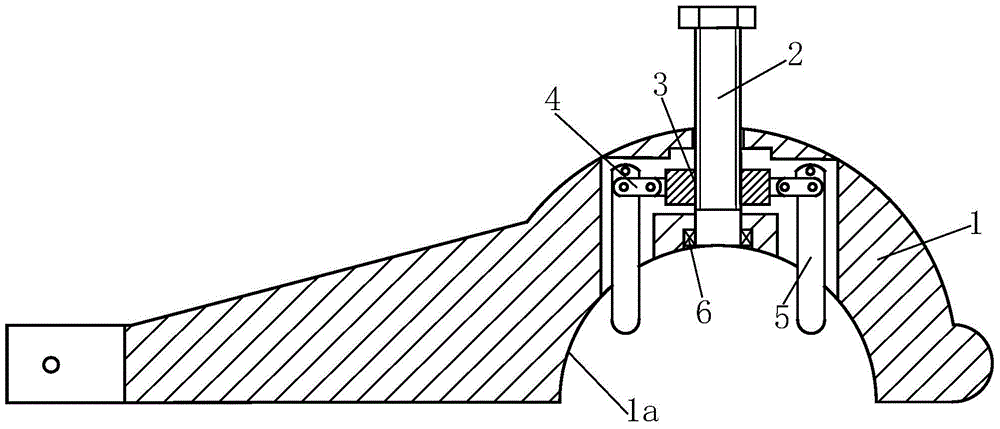
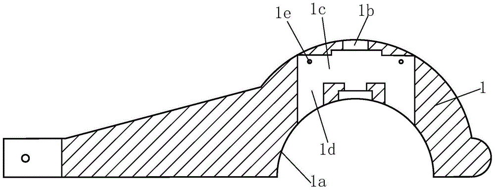
[0016] like Figure 1 to Figure 2 As shown, an adjustable clamping aid for grinding holes, including a pressure rod 1, the right part of the pressure rod 1 is provided with an arc-shaped inner recess 1a, and the upper center of the arc-shaped inner recess 1a is provided with a penetrating The outer connection hole 1b of the pressure rod 1, the middle part of the outer connection hole 1b is provided with an upper swing cavity 1c perpendicular to the outer connection hole 1b, and the left and right ends of the upper swing cavity 1c are symmetrically opened with the upper swing cavity 1c. The vertically connected lower pendulum cavity 1d, the upper part of the lower pendulum cavity 1d is provided with a hanger pin 1e. Depression bar 1 is used as the substrate that other parts are installe...


PUM


Abstract

The invention relates to an adjustable clamping auxiliary tool for grinding a hole. The adjustable clamping auxiliary tool comprises a press rod; an arc-shaped concave part is arranged at the right of the press rod; an external connecting hole passing through the press rod is formed in the center of the upper part of the arc-shaped concave part; an upper swing cavity which vertically penetrates through the external connecting hole is arranged in the middle of the external connecting hole; two lower swing cavities which are vertically communicated with the upper swing cavity are respectively and symmetrically arranged at the left end and the right end of the upper swing cavity; a hanging pin is arranged at the upper part of the each lower swing cavity; an angle adjusting stud is arranged in the external connecting hole; the lower end of the angle adjusting stud is connected with the press rod by a bearing; the upper swing cavity is internally provided with an angle adjusting screw, the lower swing cavities are respectively and internally provided with a swing pressure pin; the upper ends of the swing pressure pins are articulated with the hanging pins; pull rods are respectively arranged between the middle upper parts of the swing pressure pins and the angle adjusting screw. The adjustable clamping auxiliary tool has the advantages that the auxiliary tool is better in flexibility, convenient to operate and control, reasonable in structural design, and the like, is capable of accurately locating and clamping a brake hydraulic cylinder in an auxiliary way, can adjust the self locating size according to the change of the type of the brake hydraulic cylinder, and is wider in application scope and compact in structure; the whole spatial size is reduced.

Description

technical field [0001] The invention relates to a clamping auxiliary device for grinding holes of a brake hydraulic cylinder, in particular to an adjustable clamping auxiliary device for grinding holes. Background technique [0002] When grinding the hole of the brake hydraulic cylinder body, it is necessary to use a positioning and pressing device to position and clamp the brake hydraulic cylinder body, and then the hole grinding process can be carried out. However, due to the special shape of the outer surface of the brake hydraulic cylinder, its structure is arc-like, and it is difficult to locate it by the traditional plate pressing method, because the contact between the pressure plate and the upper part of the brake hydraulic cylinder is a line contact , can only position the up and down position of the brake hydraulic cylinder, that is, the vertical direction perpendicular to the inner wall of the piston cylinder, but cannot limit its left and right position, that is,...

Claims


Application Information

Patent Timeline
Patent Type & Authority Patents(China)
IPC IPC(8): B24B41/06
CPCB24B41/06
Inventor 夏坤财
Owner 山东飞宏工程机械有限公司
Learn More