Light far and near light dimming control circuit

A technology for changing light and controlling circuits for far and near light, which is applied in the direction of optical signals, vehicle components, signal devices, etc., and can solve the problems of the lack of versatility of far and near light control circuits, improve reliability and stability, and solve overheating Effect

Inactive Publication Date: 2017-02-15
卢颖钰
View PDF6 Cites 0 Cited by
  • Summary
  • Abstract
  • Description
  • Claims
  • Application Information

AI Technical Summary

Problems solved by technology

[0004] For this reason, the technical problem to be solved by the present invention is the problem that the far and low beam control circuit of the car lamp does not have universality when the power supply of the automobile headlight is divided into a positive pole dimming power supply and a negative pole dimming power supply. High and low light control circuit for car lamps for positive dimming power supply and negative pole dimming power supply

Method used


Image

  • Light far and near light dimming control circuit

Examples


Embodiment 1

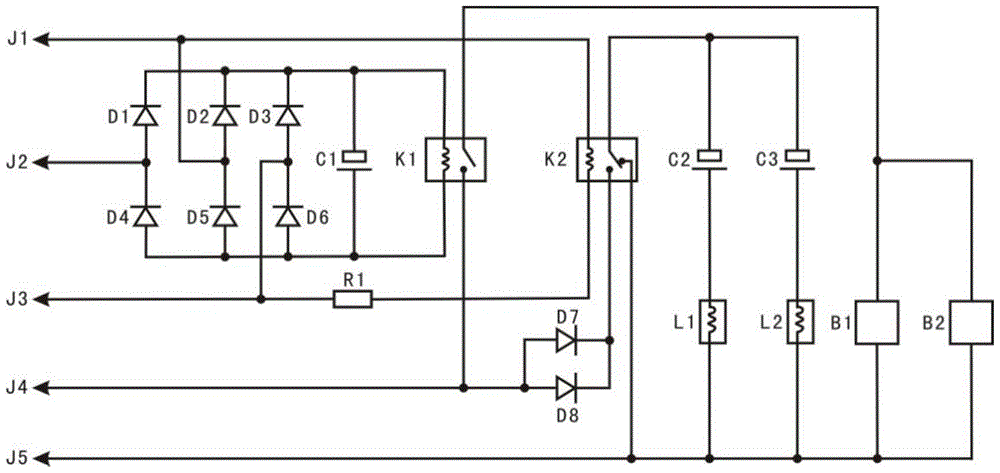
[0026] Such as figure 1 As shown, this embodiment provides a car light dimming control circuit, including a power supply circuit, a solenoid valve control circuit and an electronic ballast control circuit respectively connected to the power supply circuit. The electronic ballast control circuit includes a first The relay and the electronic ballast controlled by it; the solenoid valve control circuit includes the second relay and the solenoid valve circuit connected to it, the power circuit includes the low beam control terminal, the high beam control terminal and the common terminal, the low beam control terminal, the high beam control terminal The terminal and the common terminal are respectively connected to the two ends of the coil of the first relay through the positive conducting part and the negative conducting part, and the common terminal and the high beam control terminal are respectively connected to the two ends of the coil of the second relay. Regardless of whether...

Embodiment 2

[0033] This embodiment provides a far and near light dimming control circuit for a car lamp, which includes a power supply circuit, a solenoid valve control circuit and an electronic ballast control circuit respectively connected to the power supply circuit.

[0034] The power supply circuit includes a high beam control terminal, a low beam control terminal, a common terminal and diodes D1-D6. The diode D1 and the diode D4, the diode D2 and the diode D5, the diode D3 and the diode D6 are connected in parallel in parallel, that is, the anode of the diode D1 and the cathode of the diode D4, the anode of the diode D2 and the cathode of the diode D5, and the diode D3 After the anode is connected to the cathode of the diode D6 respectively, the cathode of the diode D1 is connected to the cathode of the diode D2 and the cathode of the diode D3, and the anode of the diode D4 is connected to the anode of the diode D5 and the anode of the diode D6. The connection of diode D1 and diode ...


PUM


Abstract

The invention provides a car lamp far-near light switching control circuit and belongs to the technical field of cars. The car lamp far-near light switching control circuit comprises a power supply circuit, a solenoid valve control circuit and an electronic ballast control circuit. The solenoid valve control circuit and the electronic ballast control circuit are connected with the power supply circuit respectively. The electronic ballast control circuit comprises a first relay and an electronic ballast controlled by the first relay. The solenoid valve control circuit comprises a second relay and a solenoid valve circuit. The power supply circuit comprises a near light control end, a far light control end and a common end which are connected to the two ends of the first relay through positive electrode conducting parts and negative electrode conducting parts respectively. The common end and the far light control end are connected with the two ends of a coil of the second relay respectively. The problem that a car light switching power supply is divided into a positive electrode light switching power supply and a negative electrode light switching power supply, so that a light switching control circuit has no universality is solved, in addition, the problem that a relay is too high in temperature is solved, and the reliability and the stability of the relays are greatly improved.

Description

technical field [0001] The invention relates to the field of automobiles, in particular to a dimming control circuit for far and near light of a car lamp. Background technique [0002] As we all know, the English abbreviation of high-intensity discharge lamp (HID) is commonly known as xenon lamp. This lamp is a high-tech product of current automobile headlights. It is widely used in high-end cars. But it can only be used in special lamps for high-end cars, and it cannot be used in the existing medium and low-end car H4 lamps. This is because its light source structure is different from that of ordinary H4 halogen tungsten lamps. There are two sets of filaments, one is the high beam light source, the other is the low beam light source, and the xenon lamp has only one light source, which can only be used on special lamps to bring out its advantages. [0003] At present, there are still many technical defects in the existing telescopic dimming xenon lamp control circuit. For ...

Claims


Application Information

Patent Timeline
Patent Type & Authority Patents(China)
IPC IPC(8): B60Q1/14
Inventor 卢颖钰
Owner 卢颖钰
Why Eureka
Try Eureka