Vacuum packaging system
A technology of vacuum packaging and vacuum chamber, which is applied in the field of packaging, can solve the problem of low automation of vacuum packaging, and achieve the effect of reducing labor and realizing automation
- Summary
- Abstract
- Description
- Claims
- Application Information
AI Technical Summary
Problems solved by technology
Method used
Image

Examples
Embodiment 1
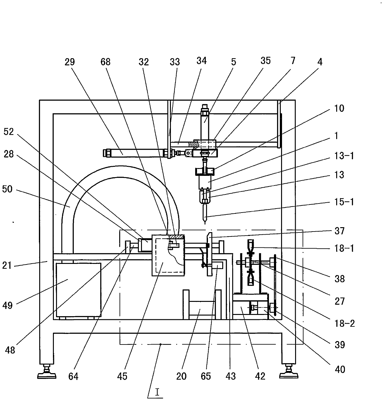
[0070] combine Figure 8 to Figure 13 A total of 6 drawings for illustration. Figure 8 is a schematic diagram of the pick-and-place mechanism in the present invention, and this figure can be compared with figure 1 combined reading; Figure 9 yes Figure 8 The top view of , the upper two dotted lines and the lower two dotted lines represent equipment racks; Figure 10 yes Figure 8 left view of Figure 11 It is a three-dimensional schematic diagram of the pick-and-place mechanism in the present invention, and the clamping strips (labels 13 and 13-1) in the figure are in the front and bottom positions; Figure 12 Figure 11 The change figure, the clamping strips (labels 13 and 13-1) in the figure are in the upper front position; Figure 13 Figure 12 The change figure of the figure, the clamping bar (label 13 and 13-1) in the figure is in the position on the back.
[0071] Explanation of symbols in the figure: left action box 1; right action box 1-1; first guide bush 2...
Embodiment 2
[0093] This example illustrates the working principles associated with the vacuum operation and the heat-melt sealing operation.
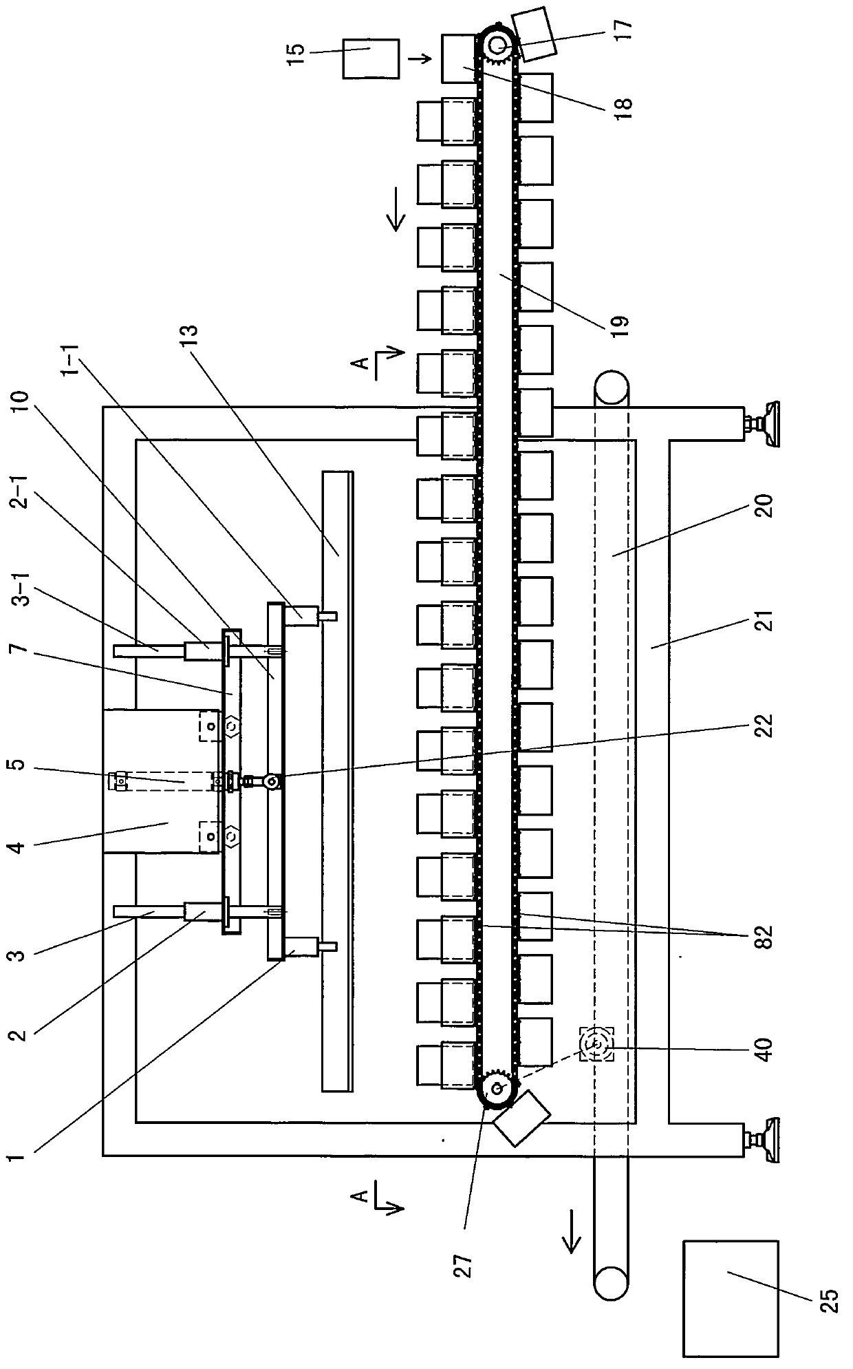
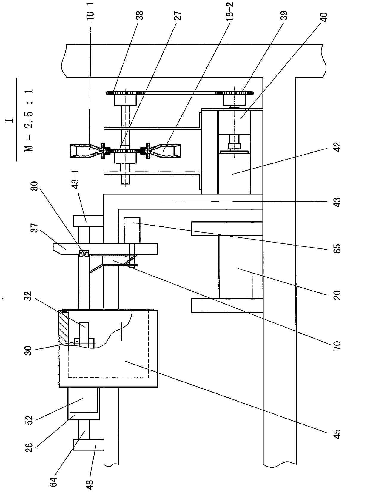
[0094] combine figure 1 , figure 2 , image 3 , not to mention the combination Figure 4 , Figure 5 , Figure 6 and Figure 7 Be explained. figure 1 It is one of the schematic diagrams of the vacuum packaging system of the present invention; the arrow in the lower left part of the figure represents: the movement direction of the finished product discharging machine 20 facing upward and the load-bearing surface is towards the left; the arrow in the right part of the figure represents: the placement box with the workpiece 15 18, its direction of movement under the load of the feed conveyor 19 is towards the left; figure 2 yes figure 1 The left side view of the figure, the main body of the vacuum chamber marked with 45 is in a separated state; image 3 yes figure 2 Partial enlarged view of I in the center, the magnification ratio is 2.5:...
Embodiment 3
[0121] The relevant situation of clamping and releasing the workpiece 15 by the front and rear clamping bars is illustrated and explained through this embodiment.
[0122] see figure 1 , the feed conveyor 19 is in a suspended motion state, and the empty placement box 18 waits for the new workpiece 15 to fall; the front clamping bar 13 and the rear clamping bar 13-1 of the pick-and-place mechanism are in the space position on the front, and the front and rear The clamping strips are in a separated state, and then the front and rear clamping strips 13 move downwards, and then close up. In this way, 10 workpieces 15 to be processed are clamped, and then, the clamping strips work together with the clamped workpieces 15. upward movement.
[0123] Just as the clamping bar moves upward together with the clamped workpiece 15, a new workpiece 15 falls into the placement box 18; when the automatic control circuit confirms that the upward movement of the clamping bar has been completed,...
PUM
 Abstract
Description
Claims
Application Information
 - R&D Engineer
- R&D Manager
- IP Professional
- Industry Leading Data Capabilities
- Powerful AI technology
- Patent DNA Extraction
Browse by: Latest US Patents, China's latest patents, Technical Efficacy Thesaurus, Application Domain, Technology Topic.
© 2024 PatSnap. All rights reserved.Legal|Privacy policy|Modern Slavery Act Transparency Statement|Sitemap