
A tile laying machine

A laying machine and ceramic tile technology, which is applied in the direction of construction and building construction, can solve the problems of low adsorption stability of suction cups, high requirements for tiles, and tile throwing out, etc., to achieve automatic construction, wide variety, and fast laying Effect

Inactive Publication Date: 2016-07-13
何敏
View PDF5 Cites 2 Cited by
  • Summary
  • Abstract
  • Description
  • Claims
  • Application Information

AI Technical Summary

Problems solved by technology

However, due to the different specifications of the tiles, the surface often has small holes, and the stability of the suction cup is not high, especially when laying tiles with uneven surfaces, the tiles are easy to be thrown out when rotating, resulting in waste, so it is necessary for laying Ceramic tiles have high requirements and poor adaptability

Method used


Image

  • A tile laying machine
  • A tile laying machine
  • A tile laying machine

Examples


Embodiment 1

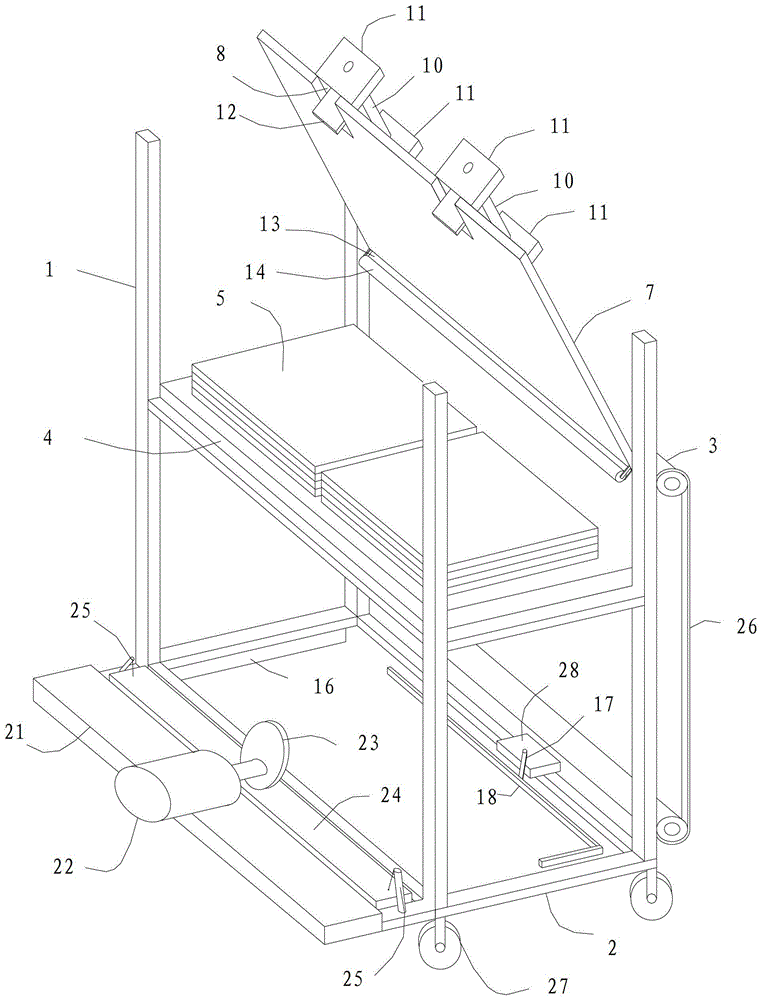
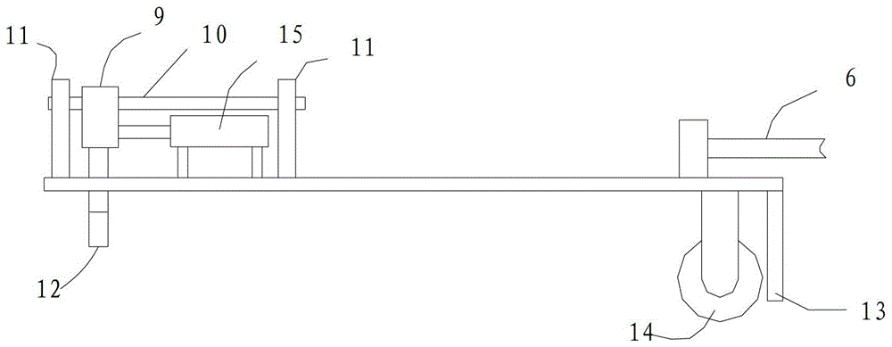
[0023] refer to Figure 1-3 , a tile laying machine, including a main frame 1 with wheels 27 at the bottom, a concrete slurry laying mechanism, a walking mechanism, etc. (not shown in the figure), wherein the upper part of the main frame 1 is provided with a tile placement platform 4 for placing tiles 5 , the bottom is provided with a construction frame 2 for laying tiles 5, and a lifting frame 3 is provided on one side of the main frame 1, and the lifting frame 3 is started by a sprocket 26, and moves up and down between the tile placement platform 4 and the construction frame 2. Lifting frame 3 is provided with rotating arm 6, and the free end of rotating arm 6 is fixed on one side of the upper surface of turning platform 7, and the other side of turning platform 7 is provided with the slot extending toward rotating arm 6 side direction. 8. Along the slot 8, a guide rail 10 fixed by the guide rail fixing seat 11 is provided on the upper surface of the turning table 7. The sl...

Embodiment 2

[0029] refer to Figure 4, is another kind of ceramic tile laying machine, and its difference from Embodiment 1 is that a flat push rod 19 and a flat push mechanism 20 are arranged on three adjacent sides of the construction frame 2, and the flat push rod 19 is connected to the flat push rod 19. Push the end of the mechanism 20. When flattening, the three horizontal pushing mechanisms 20 can simultaneously drive the horizontal pushing rods 19 to move inside the frame to squeeze and align the tiles, and can also drive the horizontal pushing rods 19 to move sequentially, which is suitable for more precise leveling and alignment requirements. Other technical features are the same as those in Embodiment 1, and will not be repeated here.


PUM


Abstract

The invention discloses a ceramic tile laying machine, which comprises a main frame provided with an upper tile placing platform and a bottom construction frame, a lifting frame is arranged on one side of the main frame, and a lifting frame is hinged on one side of the main frame. Turning platform, the other side of the turning platform is provided with a slot extending to one side of the lifting frame, along the slot is provided with a slider driven by a drive mechanism, and on the lower surface of the turning platform on the hinged side, a There is a fixed clamping piece, and an L-shaped movable clamping head extending to the lower surface of the turning table and matching with the fixed clamping piece is arranged on the slider. The invention has the advantages of fast laying, accurate positioning, adaptability to various types of ceramic tiles, convenient operation, safe and reliable use, effective reduction of operation intensity, and convenient realization of automatic construction.

Description

technical field [0001] The invention relates to the technical field of construction machinery, in particular to a ceramic tile laying machine. Background technique [0002] For many years, the tile laying of building floors and slabs has been done manually. Manual laying needs to be laid out first, and then aligned, moved closer and compacted piece by piece. The labor intensity is high and the construction efficiency is low. Higher requirements. In order to simplify the ceramic tile laying process and reduce the labor intensity of the operator, there have been special equipment for tile laying. [0003] The usual tile laying machine includes a main frame with a tile placement platform on the upper part, a construction frame at the bottom of the main frame, and a lifting frame on one side of the main frame. A rotating arm is hinged on the lifting frame, and the free end of the rotating arm There is a vacuum suction cup on the top, when the lifting frame is raised to the til...

Claims


Application Information

Patent Timeline
Patent Type & Authority Patents(China)
IPC IPC(8): E04F21/18E04F21/22
Inventor 何敏
Owner 何敏
Learn More