
Fan and impeller thereof

An impeller and fan technology, which is applied to parts of pumping devices for elastic fluids, non-variable pumps, pump devices, etc., can solve problems such as falling off of balance parts 13, accumulation of dirt, and affecting fan characteristics, and achieve The effect of smooth gas flow field, avoiding accumulation of dirt and maintaining stability

Active Publication Date: 2014-12-24
DELTA ELECTRONICS INC
View PDF4 Cites 3 Cited by
  • Summary
  • Abstract
  • Description
  • Claims
  • Application Information

AI Technical Summary

Problems solved by technology

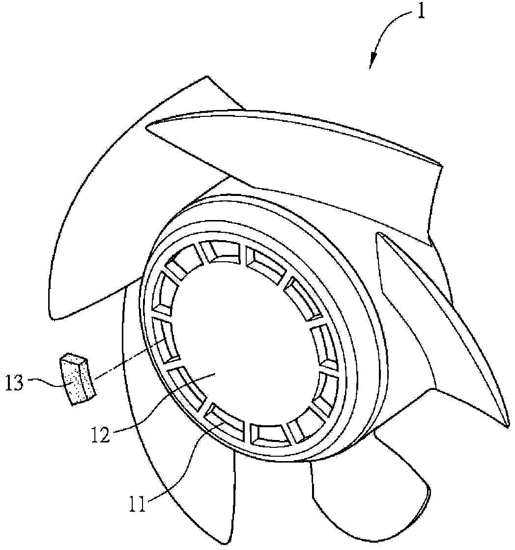
However, since this design is an open structure, during the movement of the fan, the added balance piece 13 will often break away due to the action of inertial force, losing the function of correcting the balance of the fan, and causing the excessive vibration of the fan to cause mass bad
Therefore, when the known technology is applied to actual production, it is necessary to recast the mold for the balance piece 13, and the mold must be quite accurate, so that the balance piece 13 can be kept in a tightly fitted state when it is placed in the groove 11, otherwise, the fan will move. may cause the balance piece 13 to fall off
In addition, the plurality of exposed grooves 11 will also affect the performance of the fan and accumulate dirt

Method used


Image

  • Fan and impeller thereof
  • Fan and impeller thereof
  • Fan and impeller thereof

Examples


Embodiment Construction

[0047] A fan and its fan frame according to preferred embodiments of the present invention will be described below with reference to related drawings, wherein the same components will be described with the same reference symbols.

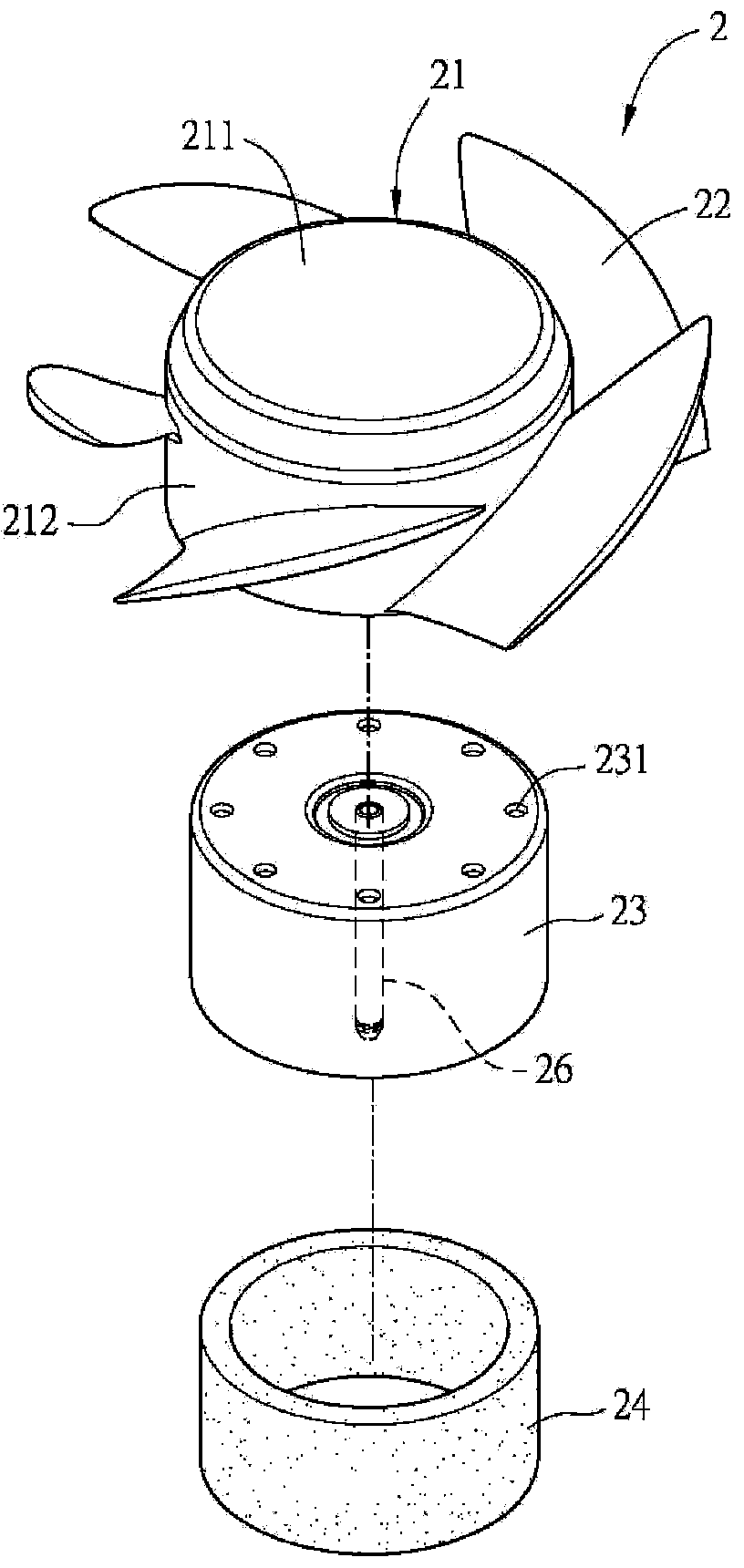
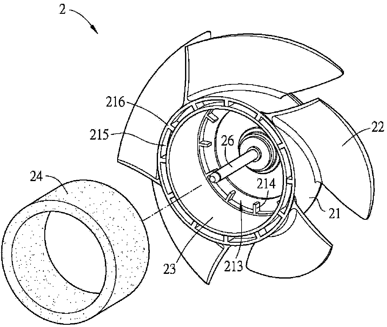
[0048] figure 2 It is an exploded schematic view of the impeller according to the first embodiment of the present invention, image 3 for figure 2 The schematic diagram of the combination of the hub and the permanent magnet shown, please also refer to figure 2 and image 3 shown. The impeller 2 according to the first embodiment of the present invention includes a hub 21 , a plurality of blades 22 , a magnetic shell 23 and a permanent magnet 24 . Wherein, the hub 21 has a top 211 and a side wall 212 , and the fan blade 22 extends outward from the side wall 212 . The hub 21 has a plurality of first balance spaces 213 on the inner side of the top 211 adjacent to the side wall 212. In the first embodiment of the present invention, the hub 21 fur...


PUM


Abstract

The invention provides an impeller of a fan and the fan. The impeller comprises a hub, a plurality of fan blades, a magnetic conduction shell and a permanent magnet. The hub is provided with a top and a side wall; a plurality of first balance spaces are arranged on the inner side, close to the side wall, of the top of the hub. The fan blades are arranged around the hub. The magnetic conduction shell is correspondingly arranged on the inner side of the hub. The permanent magnet is annularly arranged on the inner side of the magnetic conduction shell, and at least part of the first balance spaces is clamped between the top of the hub and the permanent magnet.

Description

technical field [0001] The invention relates to a fan, in particular to an impeller of the fan. Background technique [0002] With the ever-increasing demand for system cooling characteristics, fans of various sizes are increasingly used. The function of the fan is that it can drive the air flow when it is running, thereby generating heat convection to achieve the purpose of cooling the heating element. In the general fan structure, a plurality of fan blades are formed outwardly on the hub of the fan to guide the air flow during rotation. However, if the center of gravity of the fan is shifted, shaking or vibration will occur when the fan rotates. [0003] The shaking or vibration mentioned above will not only cause the fan to generate noise, but may also cause the shaft of the fan to accelerate fatigue and shorten the service life of the fan, or cause poor heat dissipation performance, thereby reducing the overall quality of the product using the fan. The current solution...

Claims


Application Information

Patent Timeline
Patent Type & Authority Applications(China)
IPC IPC(8): F04D29/32F04D25/08
CPCF04D19/002F04D25/064F04D29/662
Inventor 叶时行
Owner DELTA ELECTRONICS INC
Learn More