Heat storage system used for solar photo-thermal power generation system and control method of heat storage system

A heat storage system and photothermal power generation technology, which is applied in solar thermal power generation, mechanical power generation with solar energy, solar thermal devices, etc. question

Active Publication Date: 2014-12-24
DONGFANG ELECTRIC CORP LTD
View PDF6 Cites 8 Cited by
  • Summary
  • Abstract
  • Description
  • Claims
  • Application Information

AI Technical Summary

Problems solved by technology

The above-mentioned methods are similar to the existing ones, and cannot maximize the use of solar energy resources, resulting in the solar thermal power generation system not capturing solar energy at its maximum capacity during the time when solar light resources are the most abundant, resulting in a decline in the efficiency of solar thermal power generation and economical reduction

Method used


Image

  • Heat storage system used for solar photo-thermal power generation system and control method of heat storage system
  • Heat storage system used for solar photo-thermal power generation system and control method of heat storage system
  • Heat storage system used for solar photo-thermal power generation system and control method of heat storage system

Examples


Embodiment 1

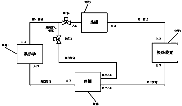
[0026] A heat storage system for a solar thermal power generation system includes a heat collection field, a heat tank, a cold tank and a heat exchange device, the outlet of the heat collection field is connected to a pipeline valve A through a first pipeline, and then the pipeline valve A connected to the inlet of the hot tank; the outlet of the hot tank is connected to the inlet of the heat exchange device through a second pipeline; the outlet of the heat exchange device is connected to the first inlet of the cold tank through a third pipeline; The outlet of the cold tank is connected to the inlet of the heat collection field through the fourth pipeline, and the outlet of the heat collection field is connected to the bypass seventh pipeline through the first pipeline, and then connected to the pipeline valve through the bypass seventh pipeline B is connected to the second inlet of the cold tank through the sixth pipeline through the pipeline valve B.

Embodiment 2

[0028] A heat storage system for a solar thermal power generation system includes a heat collection field, a heat tank, a cold tank and a heat exchange device, the outlet of the heat collection field is connected to a pipeline valve A through a first pipeline, and then the pipeline valve A connected to the inlet of the hot tank; the outlet of the hot tank is connected to the inlet of the heat exchange device through a second pipeline; the outlet of the heat exchange device is connected to the first inlet of the cold tank through a third pipeline; The outlet of the cold tank is connected to the inlet of the heat collection field through the fourth pipeline, and the outlet of the heat collection field is connected to the bypass seventh pipeline through the first pipeline, and then connected to the pipeline valve through the bypass seventh pipeline B is connected to the second inlet of the cold tank through the sixth pipeline through the pipeline valve B. The heat transfer medium...

Embodiment 3

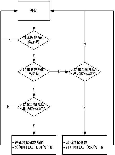
[0030] A control method for a heat storage system of a solar thermal power generation system,

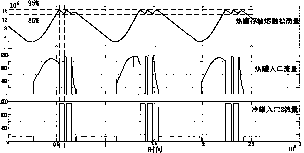
[0031] In the first step, the mass m of molten salt stored in the hot tank at the current moment is used as a reference input, and the upper limit of molten salt stored in the hot tank is set to M max , the lower limit of storing molten salt is M min , and 0≤M min ≤M max ;

[0032] When the solar radiation heats the heat collecting field and the molten salt stored in the hot tank has reached the upper limit, that is, m≥M max , close the pipeline valve A at the inlet of the hot tank, and open the pipeline valve B configured at the second inlet of the cold tank at the same time, so that the heated molten salt can flow into the cold tank;

[0033] In the second step, after the molten salt is imported into the cold tank, when the molten salt stored in the hot tank is between the upper and lower limits of the set hot tank storage molten salt, that is, M min max When , the control s...


PUM


Abstract

The invention relates to the technical field of solar photo-thermal power generation and particularly relates to a heat storage system used for a solar photo-thermal power generation system and a control method of the heat storage system. The heat storage system comprises a heat collection field, a hot tank, a cold tank and a heat exchanging device, wherein the outlet of the heat collection field is connected with a pipeline valve A by a first pipeline and is connected with the inlet of the hot tank through the pipeline valve A; the outlet of the hot tank is connected with the inlet of the heat exchanging device by a second pipeline; the outlet of the heat exchanging device is connected with the first inlet of the cold tank through a third pipeline; the outlet of the cold tank is connected with the inlet of the heat collection field by a fourth pipeline. The heat storage system and the control method mainly aim at arranging a cold and hot tank device for storing melted salt in the solar photo-thermal power generation system, and a bypass communicated with the cold tank is additionally arranged at the inlet of the hot tank; excess solar energy can be stored and utilized to the greatest extent by controlling the flowing direction of the melted salt under the condition that the illumination intensity is excess; meanwhile, the storage liquid level of the hot tank is effectively controlled.

Description

technical field [0001] The invention relates to the technical field of solar thermal power generation, in particular to a heat storage system for a solar thermal power generation system and a control method thereof. Background technique [0002] Solar thermal power generation is a clean energy method that can be concentrated for large-scale power generation. The trough system is currently among the solar thermal power generation methods, with the highest degree of technical maturity and commercialization verification. The heat source required for solar thermal power generation all comes from sunlight, and the intensity of sunlight at various time points in a day is very different. When the solar energy absorbed by the system cannot meet the heat required by solar thermal power generation, the power generation of the steam turbine will be reduced. Unstable, causing a huge impact on the power grid. How to ensure the continuous and stable power generation of solar thermal pow...

Claims


Application Information

Patent Timeline
IPC IPC(8): F24J2/34F24J2/46F03G6/06
CPCY02E10/46
Inventor 吴建东刘征宇周宏林冯玲
Owner DONGFANG ELECTRIC CORP LTD
Why Eureka
Try Eureka