A multifunctional testing platform for the mechanical properties of concrete poles
A technology for testing platforms and concrete poles, applied in the direction of applying stable tension/pressure to test the strength of materials, etc., can solve problems such as inability to load poles, unguaranteed safety and scientificity, inconvenient installation, etc., to achieve guarantee Safety and scientificity, improved quality control level, convenient and fast placement
- Summary
- Abstract
- Description
- Claims
- Application Information
AI Technical Summary
Problems solved by technology
Method used
Image
Examples
Embodiment 1
[0039] Embodiment 1: Simply supported horizontal loading mechanical performance detection, such as Figure 8 As shown, the two fixed boxes are placed left and right in the prefabricated foundation pit, and the third U-shaped skid 18 and the fourth U-shaped skid 21 are fixedly connected to the fourth fixed box 30 and the third fixed box 22 respectively. On the side, the second rolling bracket 19 and the third rolling bracket 20 with equal distances are placed in the middle of the two fixed boxes to eliminate the influence of the self-weight of the pole on the detection of the pole, and the equal-diameter pole is placed between two U-shaped skids. On the U-shaped groove, the second tension sensor 23 and the second loading device 24 are placed at the center of the pole, placed on the same side of the fixed box, and the two ends of the balance pole 36 are connected to both sides of the center of the pole to load the pole. , find a reference point on the vertical center plane of th...
Embodiment 2
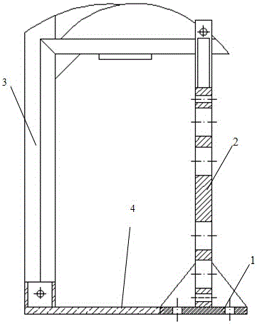
[0040] Embodiment 2: Simply supported upward loading mechanical performance detection, such asfigure 1 , Figure 5 , Figure 6 and Figure 7 , simply supported upward loading and downward loading use the same loading equipment and supporting components, change the direction of the loading point and the force of the supporting point, fix and install the two fixed boxes 7 in the prefabricated foundation pit respectively, and fix the upper end of the box 7 Fixedly connect the U-shaped hoops, clamp the two ends of the equal-diameter electric pole through two U-shaped hoops, place the jack 9 on the disc base 4, connect the pressure sensor 10 at the upper end, and connect the U-shaped skid at the upper end of the pressure sensor 10, The U-shaped skid is placed at the center of the pole, and a reference point is found on the horizontal center plane of the pole as the zero point, and the switch button of the jack 9 is activated to push the jack 9 upward to transmit the force to the p...
Embodiment 3
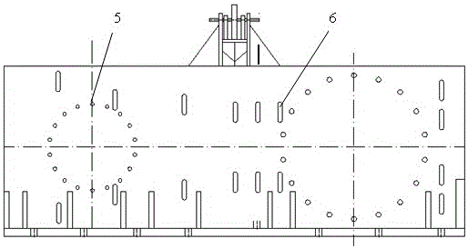
[0041] Embodiment 3: Cantilever type horizontal loading mechanical performance detection, such as figure 2 and Figure 9 As shown, place the first U-shaped skid 12 on the side of the main wall panel 2, install and fix the large end of the tapered electric pole through the U-shaped groove of the second U-shaped skid 12, and place the second U-shaped pad on the other fulcrum Wood 13, the second U-shaped skid 13 is placed on the side of the second fixed box 14, and the pole is supported by the second rolling bracket 15 at a distance from the top. The bottom surface of the second rolling bracket 15 is provided with rollers. Move easily on the top of the pole to eliminate the influence of self-weight on the detection of the pole. The first tension sensor 16 is connected to the top of the pole through a wire rope, and the first tension sensor 16 is fixedly connected to the first loading device 17. Accurate a reference line, as a zero point, start the first loading device 17, allow...
PUM
| Property | Measurement | Unit |
|---|---|---|
| length | aaaaa | aaaaa |
Abstract
Description
Claims
Application Information
 - R&D
- Intellectual Property
- Life Sciences
- Materials
- Tech Scout
- Unparalleled Data Quality
- Higher Quality Content
- 60% Fewer Hallucinations
Browse by: Latest US Patents, China's latest patents, Technical Efficacy Thesaurus, Application Domain, Technology Topic, Popular Technical Reports.
© 2025 PatSnap. All rights reserved.Legal|Privacy policy|Modern Slavery Act Transparency Statement|Sitemap|About US| Contact US: help@patsnap.com


