Machine vision detection mechanism for standard fasteners

A technology for machine vision inspection and standard fasteners, which is applied in the direction of instruments, measuring devices, and optical testing for flaws/defects. The effect of high degree of automation and high detection efficiency

Inactive Publication Date: 2014-12-24
CHONGQING YINGQUAN STANDARD PARTS
View PDF7 Cites 6 Cited by
  • Summary
  • Abstract
  • Description
  • Claims
  • Application Information

AI Technical Summary

Problems solved by technology

[0006] First, the detection mechanism can detect fewer functions, and the scope of application is narrow
For example, thread detection can only detect the presence or absence of tapping, whether the length is sufficient, etc., but cannot detect whether the thread pitch and tooth shape are qualified, and the detection accuracy is not high, and there are still high defective products after detection
[0007] Second, a detection device can only detect one type of part. Standard fastener companies generally produce a variety of parts, such as screws, nuts, bolts, etc. If automatic detection devices are used, multiple sets of different detection devices must be purchased. Device testing, enterprise production investment increased
The detection disk of the existing detection device needs to make a detection disk corresponding to each specification of the part, and the corresponding detection disk should be replaced when the parts of different specifications are to be tested, which causes problems such as increased cost of the detection device and low detection efficiency
[0009] Fourth, the existing detection device only detects defective products, and 1-2 workers are required to pack the parts that pass the test. The problems of work efficiency and labor cost of the enterprise have not been completely resolved.

Method used


Image

  • Machine vision detection mechanism for standard fasteners
  • Machine vision detection mechanism for standard fasteners
  • Machine vision detection mechanism for standard fasteners

Examples


Embodiment Construction

[0034] Below in conjunction with accompanying drawing and embodiment the present invention will be further described:

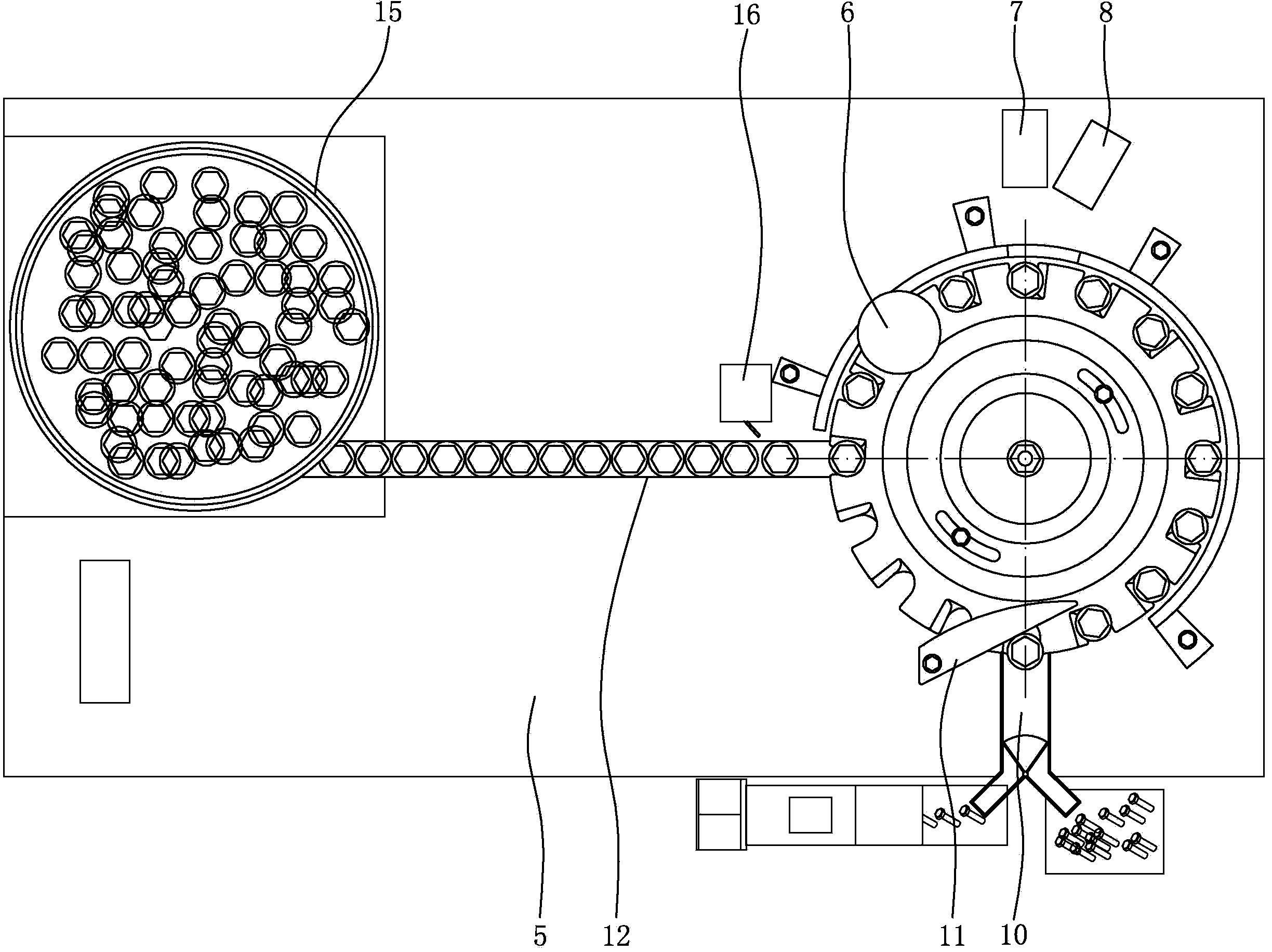
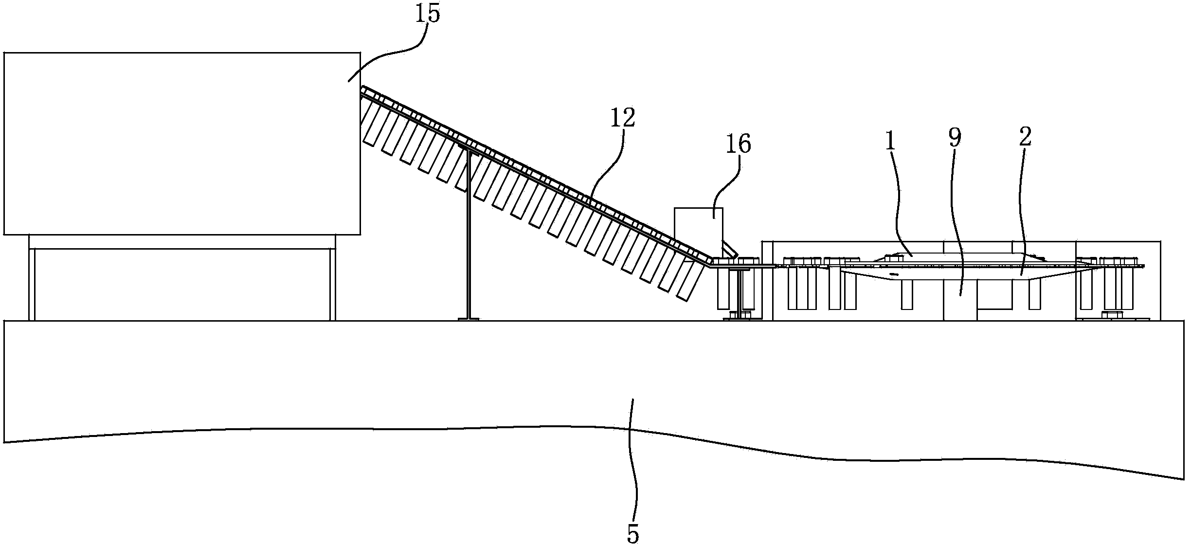
[0035] Such as figure 1 , figure 2 , Figure 5 , Figure 6 , Figure 7 and Figure 8 As shown, a vibrating plate 15 is installed at one end of the top of the machine table 5, and the vibrating plate 15 is driven by a vibrating motor. The other end of the top of the machine platform 5 is provided with an indexing turntable, which is arranged on the machine platform 5 and consists of a moving plate 1 and a fixed plate 2 . The moving plate 1 and the fixed plate 2 are disc structures with equal diameters, and the moving plate 1 is located directly above the fixed plate 2 . The middle part of the top surface of the moving disk 1 is integrally formed with a stepped boss with a small upper part and a larger lower part; The surfaces are fitted together, and the moving plate 1 and the fixed plate 2 are connected by two fastening bolts evenly distributed on the...


PUM


Abstract

The invention discloses a machine vision detection mechanism for standard fasteners. A vibrating disk (15) is arranged at one end of the top part of a machine stand (5), an indexing turntable is arranged at the other end of the top part of the machine stand (5), a guide rail (12) for conveying parts is arranged between the vibrating disk (15) and the indexing turntable, the guide rail (12) is composed of a fixed conveying rail (12a) and an adjustable conveying rail (12b), which are arranged side by side, the outlet ends of the fixed conveying rail (12a) and the adjustable conveying rail (12b) are bent upwards to form a horizontal section (12c), and a blowing device (16) is arranged on the side edge of the outlet end of the guide rail (12). The machine vision detection mechanism adopts three CCD cameras to shoot images of the parts in different angles, can be used for automatically completing conveying, detection, sorting and packaging of the standard fasteners, can be used for detecting the various standard fasteners, can be adaptive to the to-be-detected parts with different specifications, and is good in universality, high in automation degree and high in detection efficiency.

Description

technical field [0001] The invention belongs to the technical field of detection devices, and in particular relates to a standard fastener machine vision detection mechanism. Background technique [0002] In recent years, foreign countries have done a lot of research on the use of machine vision technology for quality inspection, and obtained many important results. Visual inspection has the advantages of non-contact, fast speed, high precision, strong anti-interference ability, etc. It has an important application prospect in modern manufacturing industry. With a wide range of applications, visual inspection technology provides an ideal means to solve online measurement problems. In the 1980s, the American National Bureau of Standards made a prediction based on the survey: 80% of the industrial inspection work in the future will be completed by visual inspection technology. [0003] As basic parts, standard fasteners are widely used in many industries of the national econ...

Claims


Application Information

Patent Timeline
Patent Type & Authority Applications(China)
IPC IPC(8): G01N21/88G01B11/00B07C5/34
Inventor 王咏真
Owner CHONGQING YINGQUAN STANDARD PARTS
Why Eureka
Try Eureka