A flow field maintenance method for an immersion photolithography machine

A technology of immersion lithography and lithography machine, which is applied in the direction of microlithography exposure equipment, photolithography exposure device, etc., which can solve the problems of large humidity drop and measurement system interference, and achieve the effect of reducing liquid film evaporation and cooling

Active Publication Date: 2016-12-28
SHANGHAI MICRO ELECTRONICS EQUIP (GRP) CO LTD
View PDF4 Cites 0 Cited by
  • Summary
  • Abstract
  • Description
  • Claims
  • Application Information

AI Technical Summary

Problems solved by technology

[0012] The invention provides an immersion lithography machine and its flow field maintenance method to solve the problem that the existing immersion lithography machine gas humidity drops too much and the sealing gas overflows and interferes with position measurement systems such as interferometers

Method used


Image

  • A flow field maintenance method for an immersion photolithography machine
  • A flow field maintenance method for an immersion photolithography machine
  • A flow field maintenance method for an immersion photolithography machine

Examples


Embodiment Construction

[0045] In order to make the above objects, features and advantages of the present invention more comprehensible, specific implementations of the present invention will be described in detail below in conjunction with the accompanying drawings. It should be noted that all the drawings of the present invention are in simplified form and use inaccurate scales, and are only used to facilitate and clearly assist the purpose of illustrating the embodiments of the present invention.

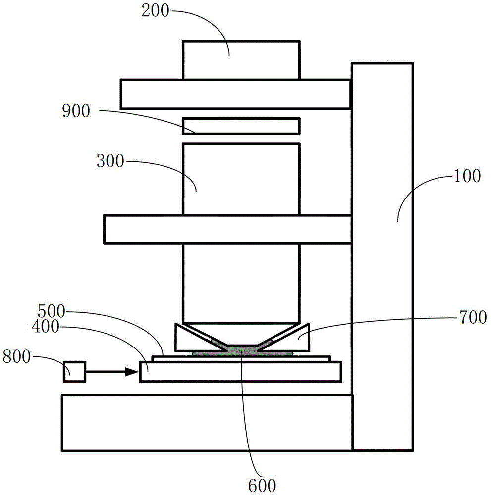
[0046] For the immersion lithography machine provided by the present invention, please refer to Figure 3 to Figure 6 , comprising a main frame 100, an illumination system 200 sequentially fixed on the main frame 100 from top to bottom, a projection objective lens 300, and a silicon wafer stage 400, on which silicon wafers coated with photosensitive photoresist are placed. piece 500, between the projection objective lens 300 and the silicon wafer 500 is filled with immersion liquid 600, between the proj...


PUM

PropertyMeasurementUnit
widthaaaaaaaaaa
widthaaaaaaaaaa

Abstract

The invention relates to an immersion photolithography machine and a method for maintaining its flow field. The structure includes a main frame, an illumination system fixed on the main frame from top to bottom, a projection objective lens, and a silicon wafer stage. The silicon wafer A silicon wafer coated with photosensitive photoresist is placed on the stage, an immersion liquid is filled between the projection objective lens and the silicon wafer, and an immersion limiting mechanism is also provided between the projection objective lens and the silicon wafer. The immersion limiting mechanism is provided with an immersion liquid supply opening, an extraction opening, and an air-tight gas inlet. The immersion liquid supply opening provides supply for the immersion liquid; the extraction opening is connected to a separate negative pressure source to provide a negative pressure for the immersion liquid. pressure; the air-tight gas inlet includes a first air-tight gas inlet and a second air-tight gas inlet, and the first air-tight gas inlet and the second air-tight gas inlet are respectively connected to a separate positive pressure source for the immersion liquid Provide positive air supply pressure. The present invention reduces exposure defects through the cooperation of two hermetically sealed gas inlets.

Description

technical field [0001] The invention relates to the field of semiconductor photolithography equipment, in particular to an immersion photolithography machine and a flow field maintenance method thereof. Background technique [0002] Modern lithography equipment is based on optical lithography, which uses an optical system to accurately project and expose the pattern on the mask to the substrate (such as: silicon wafer) coated with photoresist. Immersion lithography refers to filling water (or higher refraction immersion liquid) between the exposure lens and the silicon wafer to replace the corresponding air in traditional dry lithography technology. Since the refractive index of water is larger than that of air, this makes The numerical aperture of the lens group is increased, and a smaller characteristic line width can be obtained. [0003] However, since immersion lithography needs to fill the liquid between the lens and the silicon wafer, this brings many new technical d...

Claims


Application Information

Patent Timeline
Patent Type & Authority Patents(China)
IPC IPC(8): G03F7/20
Inventor 赵丹平张洪博聂宏飞罗晋张崇明
Owner SHANGHAI MICRO ELECTRONICS EQUIP (GRP) CO LTD
Why Eureka
Try Eureka