
Operation-handle-locking-type three-station mechanism and operation method thereof

An operating handle and locking technology, applied in the direction of air switch components, etc., can solve problems such as poor three-station structure design, and achieve the effects of good linkage effect, reasonable structure design, and convenient conversion operation

Active Publication Date: 2014-12-24
宁波剑润机电有限公司
View PDF5 Cites 5 Cited by
  • Summary
  • Abstract
  • Description
  • Claims
  • Application Information

AI Technical Summary

Problems solved by technology

[0003] In order to overcome the above disadvantages, the object of the present invention is to provide the field with an operating handle locking type three-position mechanism and its operating method, so that it can solve the three-position structure design deficiency of the operating mechanism in the existing similar high-voltage switch products. good technical questions

Method used


Image

  • Operation-handle-locking-type three-station mechanism and operation method thereof
  • Operation-handle-locking-type three-station mechanism and operation method thereof
  • Operation-handle-locking-type three-station mechanism and operation method thereof

Examples


Embodiment Construction

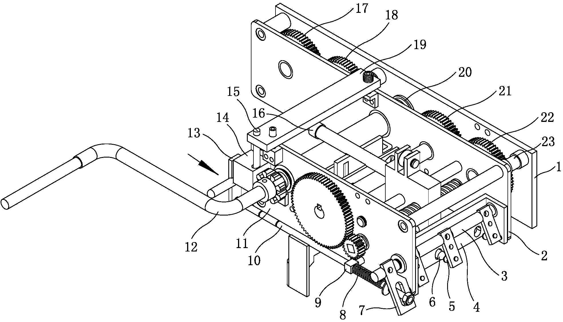
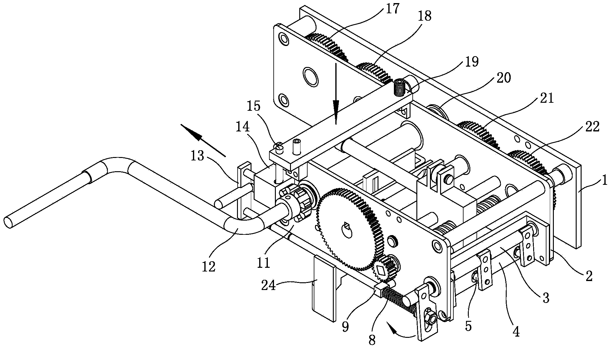
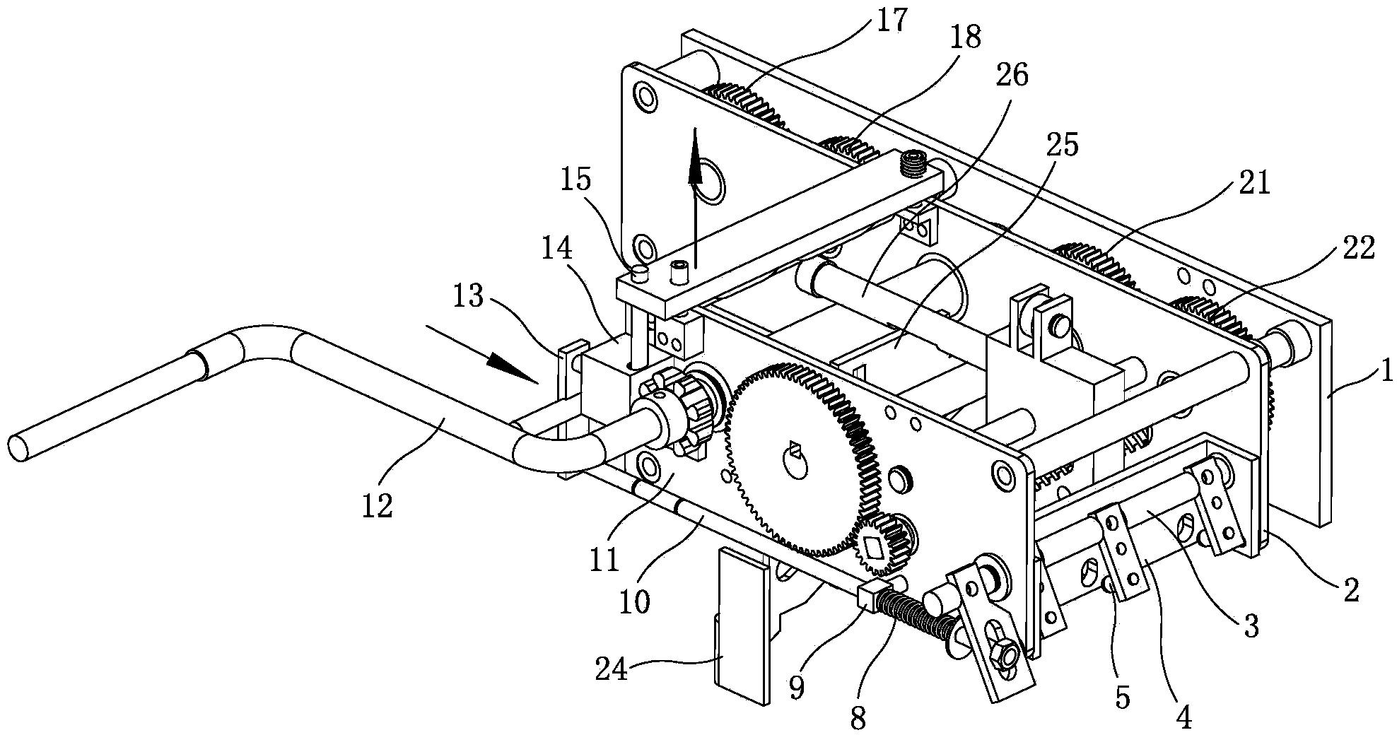
[0022] Now in conjunction with the accompanying drawings, the structure and use of the present invention will be further described. like Figure 1 to Figure 10As shown, the first mounting plate 1, the second mounting plate 2, and the third mounting plate 11 of the mechanism are respectively connected in sequence through the support shaft 23 to form a frame structure with two layers of operating gaps. The first mounting plate and the second mounting plate The first output shaft gear 17, the first transition shaft gear 18, the second output shaft gear 20, the second transition shaft gear 21 and the third output shaft gear 22, which are meshed with each other in sequence, are arranged in the operating gap between them. , The second and third output shaft gears are respectively connected to the first, second and third output shafts, the second output shaft is the driving shaft, and a station plate is provided in the operating gap between the second mounting plate and the third mou...


PUM


Abstract

The invention provides an operation-handle-locking-type three-station mechanism and an operation method of the operation-handle-locking-type three-station mechanism. The three-station mechanism is designed to solve the technical problem that a three-station structure of an operation mechanism in an existing similar high-voltage switch product is poor in design. The three-station mechanism is characterized in that a station plate of the mechanism is provided with plate holes of three stations, a locking pin on one side of a nut plate stretches out of one of the plate holes of the station plate, and the plate holes in the station plate are opposite to unlocking pins of a unlocking plate on an unlocking shaft respectively; the nut plate is fixed to the position between a second installation plate and a third installation plate through a lead screw and a nut shaft, and a lead screw gear arranged at the end, stretching out of the third installation plate, of the lead screw is meshed with a front gear. A locking pin plate at one end of the unlocking shaft is connected with one end of an unlocking rod arranged on the outer side of the third installation plate. A spring under the locking state and the station conversion state is in an original state. One end of the unlocking rod stretches out of a slide hole of the locking pin plate. The other end of a first unlocking piece at the other end of the unlocking rod is provided with a limiting shaft, the limiting shaft is meshed with a limiting gear of a rocking handle through a guide housing shell, and the first unlocking piece is provided with a handle shaft.

Description

technical field [0001] The invention relates to a three-station mechanism of a high-voltage switch, which is an operating handle locking type three-station mechanism and an operating method thereof. Background technique [0002] A high-voltage switch, or a high-voltage circuit breaker, can not only cut off or close the no-load current and load current in the high-voltage circuit, but also cut off the overload current and short-circuit current through the function of the relay protection device when the system fails. Perfect arc extinguishing structure and sufficient breaking capacity. The operation process mainly involves controlling the three stations of closing, opening and grounding of the high-voltage switch, that is, when the operating mechanism is in the closing position, the grounding operation cannot be performed, and when it is in the grounding position, the closing operation cannot be performed; thus Ensure the safety of the operating mechanism of the high-voltage...

Claims


Application Information

Patent Timeline
Patent Type & Authority Applications(China)
IPC IPC(8): H01H31/04
Inventor 胡光福常秀文王世孝
Owner 宁波剑润机电有限公司
Learn More