A snap-on relay

A relay, one-to-one correspondence technology, applied in the direction of relays, electromagnetic relays, detailed information of electromagnetic relays, etc., can solve the problems of high maintenance and replacement costs, high glue costs, and bottom plate falling off, so as to simplify fastening installation and ensure installation Strength and aesthetic improvement effect

Active Publication Date: 2016-04-13
NINGBO YINZHOU YONGLIN ELECTRON ELECTRICAL EQUIP
View PDF3 Cites 0 Cited by
  • Summary
  • Abstract
  • Description
  • Claims
  • Application Information

AI Technical Summary

Problems solved by technology

[0004] Some of the prior art relays are connected by sealing glue between the bottom plate and the outer shell, which will cause the bottom plate to fall off after long-term use, and the cost of the glue is relatively high; or some are welded, and the relay needs to be sealed during use. For repair and replacement, welding will cause high cost of repair and replacement, laborious disassembly

Method used


Image

  • A snap-on relay
  • A snap-on relay
  • A snap-on relay

Examples


Embodiment Construction

[0025] The following are specific embodiments of the present invention and in conjunction with the accompanying drawings, the technical solutions of the present invention are further described, but the present invention is not limited to these embodiments.

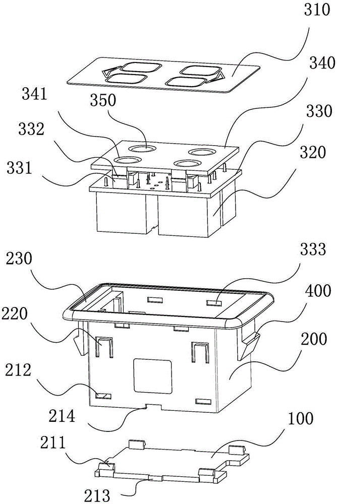
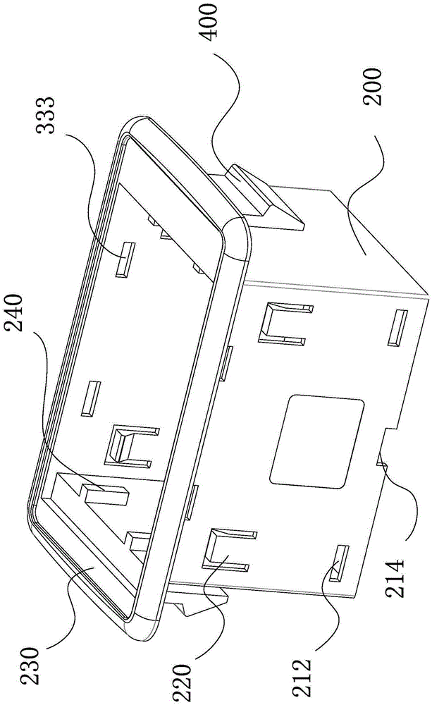
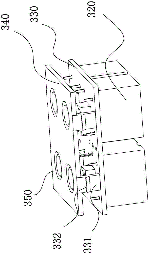
[0026] Such as Figure 1 to Figure 4 As shown, the clip-on relay includes a bottom plate 100, an outer casing 200 and a control assembly. The control assembly includes a control panel 310 clamped on the top of the outer casing 200 and a plurality of control coils 320 installed in the outer casing 200. The bottom plate 100 passes through The buckle structure is fastened on the bottom of the outer casing 200, the buckle structure includes a locking piece and a positioning piece, the locking piece includes a number of hooks 211 fixedly connected to the bottom plate 100 and a number of slots 212 corresponding to the hooks 211 one by one , the hook 211 is set in the slot 212; the positioning member includes a plurality of posit...


PUM


Abstract

The invention provides a clamping type relay and belongs to the technical field of electrical equipment. The clamping type relay solves the problem that an existing relay is unstable in connection. The clamping type relay comprises a base board, an outer shell body and a control assembly. The control assembly comprises a control panel arranged on the top of the outer shell body in a clamped mode and a plurality of control coils installed inside the outer shell body. The base board is buckled to the bottom of the outer shell body through a buckling structure. The buckling structure comprises locking pieces and locating pieces. The locking pieces comprise a plurality of clamping hooks fixedly connected to the base board and a plurality of clamping grooves in one-to-one correspondence with the clamping hooks, and the clamping hooks are arranged in the clamping grooves in a clamped mode. The locating pieces comprise a plurality of locating protruding blocks arranged on the base board and a plurality of locating grooves in one-to-one correspondence with the locating protruding blocks, and the locating protruding blocks are matched with the locating grooves. The clamping type relay has the advantages of being simple in structure, convenient to disassemble and good in connection stability.

Description

technical field [0001] The invention belongs to the technical field of electrical equipment, and relates to a clamping relay. Background technique [0002] The relay is an automatic control device whose output will change in a jump when the input quantity (electricity, magnetism, sound, light, heat, also known as excitation quantity) reaches a certain value. , is an electronic control device, it has a control system (also known as the input circuit) and a controlled system (also known as the output circuit), usually used in automatic control circuits, it actually uses a smaller current to control a larger An "automatic switch" of electric current. It plays the role of automatic adjustment, safety protection, conversion circuit and so on in the circuit. [0003] The electromagnetic relay is mainly composed of an input part and an output part. These two parts mainly include: the coil at the input end, the yoke iron, the isolation plate, the bottom plate, the iron core, the ...

Claims


Application Information

Patent Timeline
Patent Type & Authority Patents(China)
IPC IPC(8): H01H50/02
Inventor 钱小伟王林沪钱和伟
Owner NINGBO YINZHOU YONGLIN ELECTRON ELECTRICAL EQUIP
Why Eureka
Try Eureka