

Self-triggering stack stscr‑ldmos high voltage esd protection circuit
A high-voltage, stacked unit technology, applied in the electronic field, can solve the problems of low maintenance voltage, burnout devices, etc., and achieve the effect of protecting internal circuits and reducing the risk of latch-up effect
- Summary
- Abstract
- Description
- Claims
- Application Information
AI Technical Summary
Problems solved by technology
Method used
Image

Examples
Embodiment 1
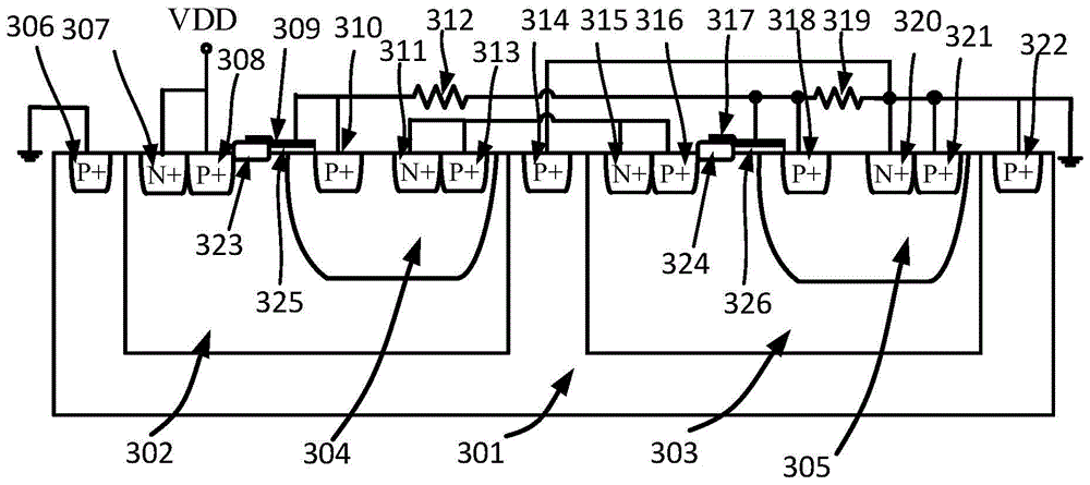
[0033] image 3 A schematic structural diagram of a self-triggering stacked STSCR-LDMOS high-voltage ESD protection circuit provided in this embodiment. A high-voltage ESD protection circuit for self-triggering stacked STSCR-LDMOS, such as image 3 As shown, it includes a P-type substrate 301, a first high-voltage N-type well region 302, a second high-voltage N-type well region 303, a first P-type heavily doped region 306, a second P-type heavily doped region 308, a third P-type heavily doped region 310, fourth P-type heavily doped region 313, fifth P-type heavily doped region 314, sixth P-type heavily doped region 316, seventh P-type heavily doped region 318, eighth P-type heavily doped region P-type heavily doped region 321, ninth P-type heavily doped region 322, first N-type heavily doped region 307, second N-type heavily doped region 311, third N-type heavily doped region 315, fourth N-type heavily doped region 320, first resistor 312, second resistor 319, first field ox...
Embodiment 2
[0044] Such as Figure 7 As shown, in this embodiment, on the basis of Embodiment 1, the second resistor 319 is removed. The working principle of this embodiment is the same as that of Embodiment 1.
[0045] Embodiment 2 removes resistor 319, so that Q 3 All the current after the breakdown flows through the resistor 404, which can increase the turn-on speed of the STSCR-LDMOS.
[0046] Figure 5 The equivalent circuit diagram of the high-voltage ESD protection circuit of the self-triggering stacked STSCR-LDMOS provided by the present invention. The present invention can greatly increase the sustain voltage by stacking more STSCR-LDMOS stacked units 501, and more effectively prevent the occurrence of latch-up effect.
[0047] Figure 6The I-V curve simulation diagram of different STSCR-LDMOS stacking numbers is given. It can be seen from the figure that as the stacking number increases, the breakdown voltage increases from 70V to 80V, and the sustain voltage increases from...
PUM
 Abstract
Description
Claims
Application Information