Dehumidification device for electrical cabinet

A technology for electrical boxes and humidity, applied to electrical components, substation/switch layout details, and separation of dispersed particles, can solve problems that endanger the safe operation of electrical equipment, and achieve the effects of improving reliability and reducing air humidity

Inactive Publication Date: 2014-12-24
STATE GRID CORP OF CHINA +1
View PDF5 Cites 3 Cited by
  • Summary
  • Abstract
  • Description
  • Claims
  • Application Information

AI Technical Summary

Problems solved by technology

[0005] The invention provides a dehumidification device for an electrical box, which is used to solve the technical problem that the heating type dehumidifier in the prior art will cause the air moisture in the electrical box to condense on the surface of the equipment due to the drop of the ambient temperature, which will endanger the safe operation of the electric equipment.

Method used


Image

  • Dehumidification device for electrical cabinet
  • Dehumidification device for electrical cabinet
  • Dehumidification device for electrical cabinet

Examples


Embodiment Construction

[0035] The following will clearly and completely describe the technical solutions in the embodiments of the present invention with reference to the accompanying drawings in the embodiments of the present invention. Obviously, the described embodiments are only some, not all, embodiments of the present invention. Based on the embodiments of the present invention, all other embodiments obtained by persons of ordinary skill in the art without making creative efforts belong to the protection scope of the present invention.

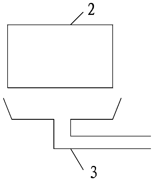
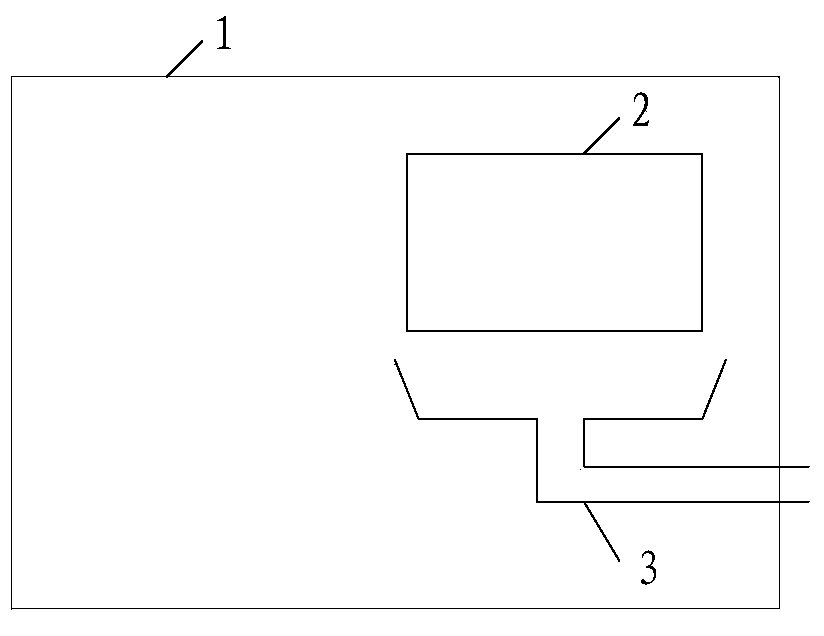
[0036] refer to figure 1 , is a structural schematic diagram of Embodiment 1 of an electrical box dehumidification device provided by the present invention, wherein the device is arranged in the electrical box 1, as figure 2 As shown in , the electrical box 1 can be box equipment such as a switch cabinet, a terminal box, a central control cabinet, a ring network cabinet, a knife mechanism box, and a cable branch box, and various electrical equipment are arran...


PUM


Abstract

The invention discloses a dehumidification device for an electrical cabinet. The dehumidification device comprises a water condenser and a drainer, wherein the water condenser is arranged in the electrical cabinet and used for condensing vapor in the electrical cabinet, and then liquid water is formed; the drainer is connected with the water condenser and used for draining the liquid water condensed through the water condenser out of the electrical cabinet. According to the dehumidification device, the water condenser is arranged in the electrical cabinet, the water condenser is used for independently condensing the vapor in the electrical cabinet, the liquid water is formed and drained out of the electrical cabinet through the drainer, the air humidity in the electrical cabinet is effectively reduced, and the water content in air in the electrical cabinet is obviously smaller than the saturation humidity ratio of the electrical cabinet, so that the situation that the vapor in air is condensed on the surface of equipment due to sharp drop of environment temperature is avoided, through the dehumidification device for the electrical cabinet, the air humidity in the electrical cabinet can be effectively reduced, the situation that water is condensed on the surface of the equipment due to drop of the external environment temperature, and safety operation of the electrical equipment is damaged is avoided, and the reliability of the electrical equipment is improved.

Description

technical field [0001] The invention relates to the technical field of electrical equipment design, in particular to an electrical box dehumidification device. Background technique [0002] If the ambient temperature and humidity are too high, the temperature rise of electrical equipment will also increase, which will easily lead to accelerated insulation aging, and in severe cases, insulation will be burned. However, if the air humidity is too high, moisture will condense on the surface of the equipment, causing mold to grow faster, reducing electrical insulation strength, and metal corrosion. Acceleration will cause the contact surface to dehumidify and the contact resistance will increase, so it is necessary to dehumidify the electrical equipment. [0003] In the prior art, a heating type dehumidifier is used to realize the dehumidification operation in the electrical box by increasing the temperature in the electrical box. However, due to the high temperature, the moist...

Claims


Application Information

Patent Timeline
Patent Type & Authority Applications(China)
IPC IPC(8): H02B1/00B01D53/26
Inventor 马益平虞勇李永腾应笑冬阮浩洁
Owner STATE GRID CORP OF CHINA
Why Eureka
Try Eureka