A device for current limiting protection of load or output

A current-limiting protection and current technology, which is applied in the direction of emergency protection circuit devices, emergency protection circuit devices, and circuit devices for limiting overcurrent/overvoltage, can solve problems such as slow response speed of current-limiting circuits, and reduce power consumption. The effects of extreme gate voltage drop, increased impedance, and fast response

Active Publication Date: 2018-03-23
INST OF MICROELECTRONICS CHINESE ACAD OF SCI
View PDF6 Cites 0 Cited by
  • Summary
  • Abstract
  • Description
  • Claims
  • Application Information

AI Technical Summary

Problems solved by technology

[0003] Usually, the current limiting current is composed of modules such as sampling, feedback, and current limiting processing. Due to the parasitic characteristics of each module, the response speed of this current limiting circuit is relatively slow, usually in the order of microseconds
And for faster current glitches, nothing can be done

Method used


Image

  • A device for current limiting protection of load or output
  • A device for current limiting protection of load or output

Examples


Embodiment Construction

[0021] In order to make the object, technical solution and advantages of the present invention clearer, the present invention will be described in further detail below in conjunction with specific embodiments and with reference to the accompanying drawings.

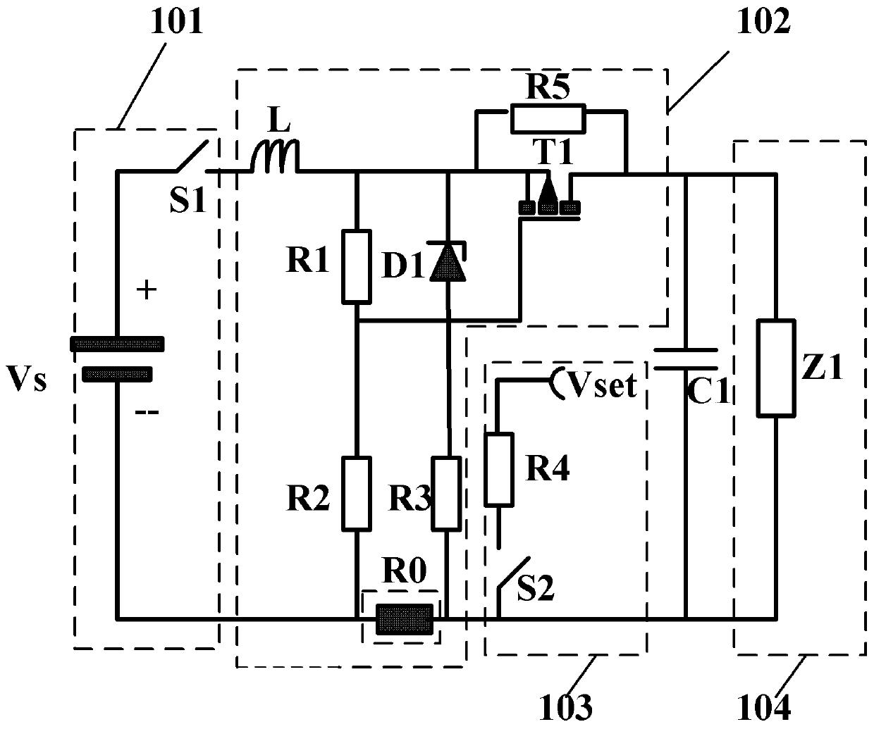
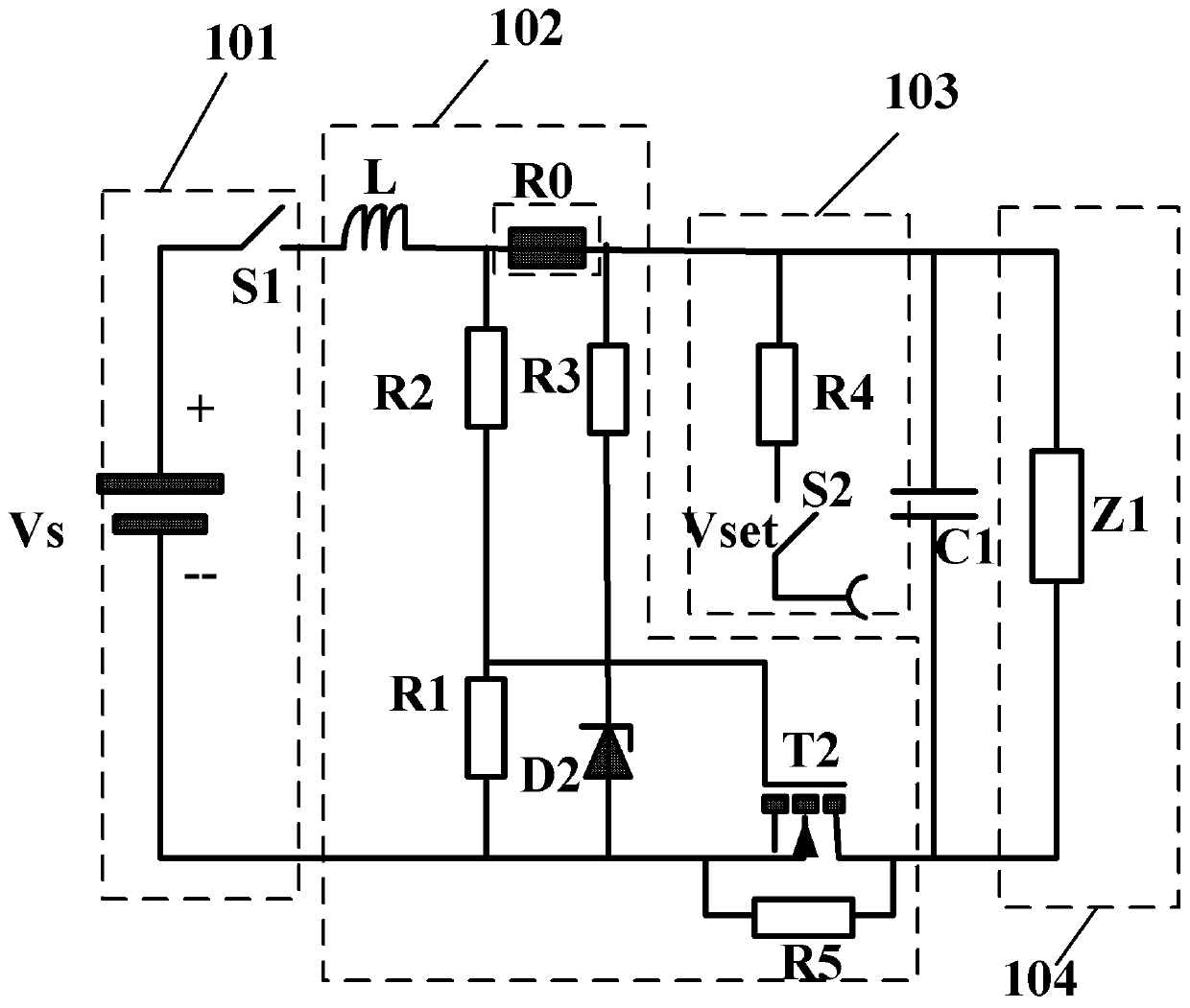
[0022] figure 1 and figure 2 Respectively provide the P-channel field effect transistor T1 according to the first and second embodiments of the present invention and the current-limiting protection device for load or output composed of the N-channel field effect transistor T2 and the zero resistance R0 of the resistive memory unit. The schematic diagram of the device, the device includes a power module 101, a current limiting circuit 102, a reset circuit 103 and a load 104, the current limiting circuit 102 includes a field effect transistor, an inductor L, the zeroth to the third resistor (R0, R1, R2, R3 ), wherein: the field effect transistor, the inductor L, the zeroth resistor R0 are connected in series with the load...


PUM


Abstract

The invention discloses a device for current limiting protection of a load or an output. The device includes a power supply module, a current limiting circuit, a reset circuit and a load. The current limiting circuit includes a field effect transistor, an inductor, and the zeroth to third resistors. Among them: the field effect transistor, the inductor, and the zeroth resistor are connected in series with the load, and the zeroth to third resistors form a feedback network with the field effect transistor. When the current exceeds the set current threshold, the resistance value of the zeroth resistor will be instantaneously changed by The low resistance value becomes high resistance value, and since the resistance value of the zeroth resistor becomes high resistance value, the feedback network formed by the zeroth to third resistor and the field effect transistor will set the gate voltage of the field effect transistor to the limit The potential of the current flow can be quickly and effectively realized to limit the current, realize the rapid response to the instantaneous large current, and effectively protect the circuit components.

Description

technical field [0001] The invention relates to the technical field of power supply or circuit protection, in particular to a device for current limiting protection of loads or outputs. Background technique [0002] Power supply or circuit protection technology is an important technology in the circuit system or equipment. Because the working environment of the power supply or circuit system is often relatively harsh, and it is often subject to external interference, the current of the system increases instantaneously, affecting the reliability and life of the circuit. For this reason, the current limiting circuit is a necessary circuit module in the power supply or power supply system. [0003] Usually, the current-limiting circuit is composed of modules such as sampling, feedback, and current-limiting processing. Due to the parasitic characteristics of each module, the response speed of this current-limiting circuit is relatively slow, usually in the order of microseconds....

Claims


Application Information

Patent Timeline
Patent Type & Authority Patents(China)
IPC IPC(8): H02H9/02
Inventor 余兆安姚志宏霍宗亮龙世兵谢常青刘明
Owner INST OF MICROELECTRONICS CHINESE ACAD OF SCI
Why Eureka
Try Eureka