
Wearable electronic device and control method and system of wearable electronic device

A technology of electronic equipment and a control method, which is applied in the direction of battery circuit devices, current collectors, electric vehicles, etc., can solve the problems of limited storage capacity of electric energy storage modules, short and long service life of wearable electronic equipment, and achieve convenience Charging use, improving user experience, and improving the effect of the use cycle

Active Publication Date: 2014-12-24
SHENZHEN SEELEN TECH
View PDF7 Cites 10 Cited by
  • Summary
  • Abstract
  • Description
  • Claims
  • Application Information

AI Technical Summary

Problems solved by technology

[0003] During the use of wearable electronic devices, it can improve the user experience and provide the data and applications people need in daily life, but there are also certain difficulties. The supply of electric energy is one of the biggest difficulties, because wearable electronic devices The volume is not suitable for large size, so the storage capacity of the electric energy storage module is limited. The small capacity of the electric energy storage module leads to a short service life of wearable electronic devices and requires frequent charging. At the same time, if the power is insufficient, the measurement data may be inaccurate. situation happened
Therefore, improving the power supply of wearable electronic devices and prolonging their service life is a problem that needs to be solved.

Method used


Image

  • Wearable electronic device and control method and system of wearable electronic device
  • Wearable electronic device and control method and system of wearable electronic device
  • Wearable electronic device and control method and system of wearable electronic device

Examples


Embodiment Construction

[0038] It should be understood that the specific embodiments described here are only used to explain the present invention, not to limit the present invention.

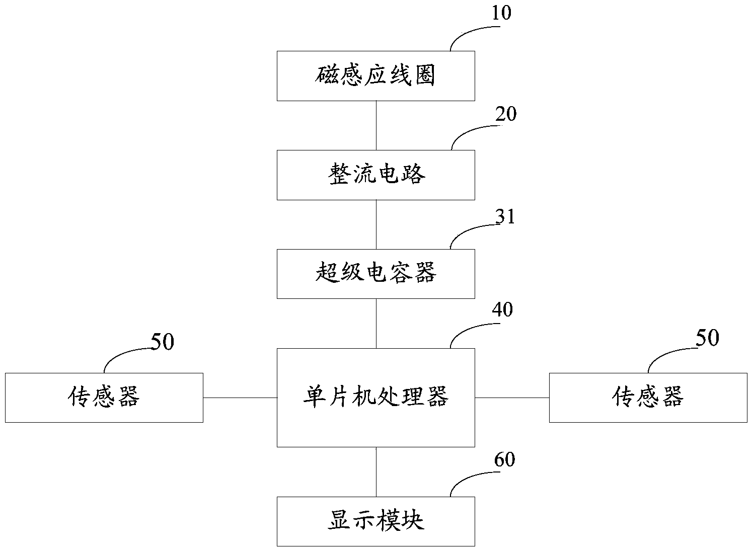
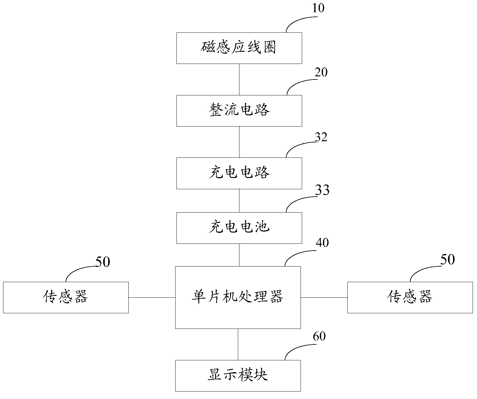
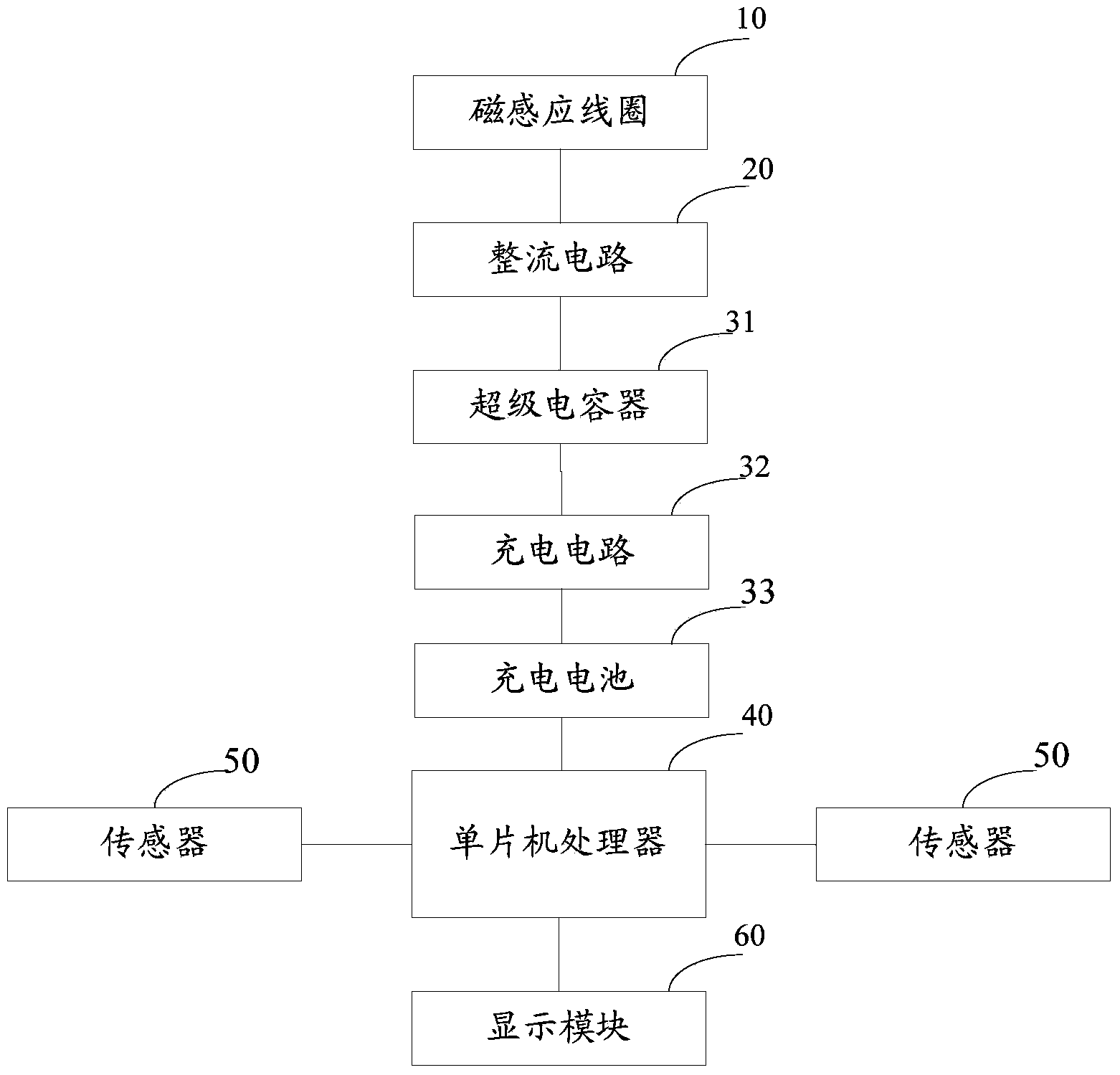
[0039] refer to figure 1 In the embodiment of the present invention, a wearable electronic device 1 is proposed. The wearable electronic device 1 generally includes conventional electronic devices such as a single-chip processor 40, a display module 60, and various functional sensors 50. The wearable electronic device The device 1 is also provided with a magnetic induction coil 10, a rectification circuit 20, and an energy storage module. The magnetic induction coil 10 is electrically connected to the rectification circuit 20, and the rectification circuit 20 is electrically connected to the energy storage module; For the induced current, the rectification circuit 20 rectifies and converts the induced current into direct current, the direct current is stored in the energy storage module, and the energy storage module ...


PUM


Abstract

The invention discloses a wearable electronic device and a control method and system of the wearable electronic device. Magnetic induction coils, a rectifying circuit and an energy storage module are arranged in the wearable electronic device. The magnetic induction coils cut magnetic lines to generate induction current. The rectifying circuit conducts rectification on the induction current and converts the induction current to direct current, the direct current is stored in the energy storage module, and the energy storage module supplies power to the wearable electronic device for operation of the electronic device. The wearable electronic device system comprises a permanent magnet and the wearable electronic device. According to the wearable electronic device control method, the preset operation is conducted according to changes of the induced electromotive force generated by collecting the magnetic induction coils. By means of the wearable electronic device and system, the using cycle of the wearable electronic device can be prolonged, and times of taking off the electronic device for charging is reduced. According to the wearable electronic device control method, the preset operation is conducted according to changes of the induced electromotive force generated by collecting the magnetic induction coils, the wearable electronic device and system are convenient to operate and flexible to control.

Description

technical field [0001] The present invention relates to the field of wearable electronic devices, in particular to a wearable electronic device, a control method and system for the wearable electronic device. Background technique [0002] Wearable electronic equipment is a general term for the application of wearable technology to intelligently design daily wear and develop wearable equipment, such as rings, glasses, gloves, watches, shoes and hats, etc., which are equipped with processors and various sensors. The communication part may also include a display module and the like. In a broad sense, wearable electronic devices include full-featured devices that do not rely on smartphones to achieve complete or partial functions, such as smart watches or smart glasses, and only focus on a certain type of application functions, which need to be used in conjunction with other devices such as smartphones. Such as all kinds of smart bracelets and smart jewelry for physical sign mo...

Claims


Application Information

Patent Timeline
Patent Type & Authority Applications(China)
IPC IPC(8): H02J7/32
CPCH02J7/32Y02B40/00
Inventor 杨松
Owner SHENZHEN SEELEN TECH
Learn More