
Eureka
For R&D, Eureka makes reading and utilizing patents & technical documents easy.
Eureka AIR
Designed for self-driven R&D workflows. Generate viable solutions, solve complex R&D challenges, empower your innovation with AI.

Eureka Materials
Designed for material experts only. Revolutionize your material R&D, from search, analyze, to developing new materials.

TechResearch
Generate reliable direction feasibility study reports for your R&D in just a few steps.

TechSeek
Discover and master advanced knowledge NOW. Basics, ideas, possibilities, all at once.

TechMind
As an expert in R&D Theories, TechMind can generates customized viable solutions instantly.

TechRisk
Analyze your overall solution with one click, know your potential R&D risks in advance.

TechMonitor
Get weekly tech updates, stay abreast of the latest tech innovations and key insights.
Holder of optical transmitter in mine
A technology of optical transmitter and fixing frame, which is applied in the direction of electromagnetic transmitters, etc., and can solve problems such as stone smashing, loose installation, and reduced service life
- Summary
- Abstract
- Description
- Claims
- Application Information
AI Technical Summary
Problems solved by technology
Method used
Image

Examples
Embodiment 1
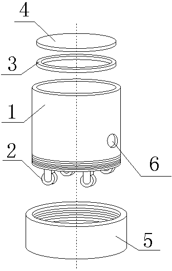
[0018] Such as figure 1 As shown, the fixed frame of the optical transmitter in the mine includes a housing 1, the housing 1 is hollow cylindrical, the upper end is open, the lower end of the housing 1 is provided with a roller 2, and the inner wall of the housing 1 is provided with a horizontal blocking ring 3, so The barrier ring 3 is provided with a protective cover 4, and the outer peripheral wall of the lower end of the housing 1 is provided with external threads, which are threaded with a roller protection ring 5. After the roller protection ring 5 rotates downward, the roller 2 Completely wrapped inside it, the outer wall of the casing 1 is provided with a wire outlet hole 6 . This device is used to place the optical transmitter. The optical transmitter is put into the casing 1, and then the protective cover 4 is covered. The protective cover is placed on the blocking ring 3, and the optical transmitter can be put into the casing 1 from the blocking ring 3. , and the s...
Embodiment 2
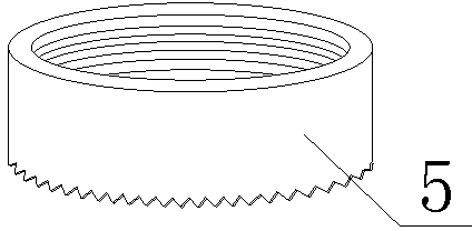
[0020] Such as figure 2 , the structure of this embodiment is basically the same as that of Embodiment 1, the difference is that the lower end of the roller protection ring 5 is a sawtooth structure, and the roller protection ring 5 is designed in a sawtooth shape, which can grip the ground more firmly and prevent the housing 1 from moving , to prevent the internal optical transmitter from colliding with the shell 1.
Embodiment 3
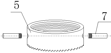
[0022] Such as image 3 , The structure of this embodiment is basically the same as that of Embodiment 2, except that the side end of the roller protection ring 5 is provided with a rotating handle 7, which facilitates the rotation of the roller protection ring 5. Turning the handle 7 thread is installed on the roller protection ring 5, the rotation handle 7 must be perpendicular to the roller protection ring 5, and the stone will be damaged if it hits it, so the rotation handle 7 is designed to be detachable, and it can be used again when needed. It is very convenient to install, and there is protection to turn the handle 7.
PUM
 Abstract
Description
Claims
Application Information
 - R&D Engineer
- R&D Manager
- IP Professional
- Industry Leading Data Capabilities
- Powerful AI technology
- Patent DNA Extraction
Browse by: Latest US Patents, China's latest patents, Technical Efficacy Thesaurus, Application Domain, Technology Topic, Popular Technical Reports.
© 2024 PatSnap. All rights reserved.Legal|Privacy policy|Modern Slavery Act Transparency Statement|Sitemap|About US| Contact US: help@patsnap.com