A method and device for interference suppression

An interference suppression and interference cell technology, which is applied in line failure/interference reduction, shaping network in transmitter/receiver, baseband system components, etc., and can solve problems such as inability to accurately estimate interference cells.

Active Publication Date: 2017-08-29
浙江杭海新城控股集团有限公司
View PDF4 Cites 0 Cited by
  • Summary
  • Abstract
  • Description
  • Claims
  • Application Information

AI Technical Summary

Problems solved by technology

[0018] Embodiments of the present invention provide an interference suppression method and device, which are used to solve the problem that the PMI corresponding to the interfering cell cannot be accurately estimated when the interference signal uses 2 ports and the number of layers is 2, or uses 4 ports and the number of layers is 4. , leading to the problem that SLIC or ML receivers cannot be used to eliminate interference

Method used


Image

  • A method and device for interference suppression
  • A method and device for interference suppression
  • A method and device for interference suppression

Examples


Embodiment Construction

[0132] The present invention considers the precoding matrix indicated by the PMI in the transmitted signal instead of considering the precoding matrix indicated by the PMI in the channel estimation, since the correct value of the PMI is not estimated during the channel estimation, thereby improving the ability of the receiver to suppress interference capability, improving the throughput performance of the terminal.

[0133] The embodiments of the present invention will be further described in detail below in conjunction with the accompanying drawings. It should be understood that the embodiments described here are only used to illustrate and explain the present invention, not to limit the present invention.

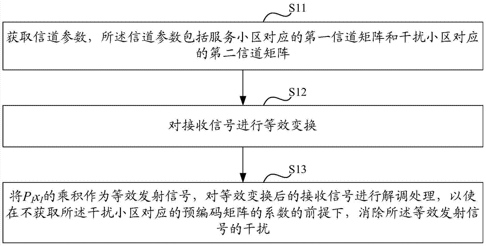
[0134] like figure 1 As shown, an interference suppression method provided by an embodiment of the present invention includes:

[0135] S11. Acquire channel parameters, where the channel parameters include a first channel matrix corresponding to the serving cell and a s...


PUM


Abstract

Disclosed are an interference suppression method and device for solving the problem that an SLIC or ML receiver cannot be used to eliminate interference because a PMI cannot be estimated precisely. The method comprises: acquiring channel parameters, which comprise a first channel matrix corresponding to a serving cell and a second channel matrix corresponding to an interfering cell; performing equivalent transformation on a received signal to obtain y=H 0 x 0 +H̃ I P I x I +n, where y is the received signal, x 0 is a first transmission signal sent by the serving cell, x I is a second transmission signal sent by the interfering cell, n is a noise signal, H 0 is the product of the first channel matrix and a pre-coding matrix corresponding to the serving cell, H̃ I is the second channel matrix, and P I is a pre-coding matrix corresponding to the interfering cell; and using the product of P I and x I as an equivalent transmission signal, and performing demodulation processing on the received signal after the equivalent transformation, so as to eliminate the interference of the equivalent transmission signal on a premise that a coefficient of the pre-coding matrix corresponding to the interfering cell is not acquired.

Description

technical field [0001] The invention relates to the field of communication technology, in particular to an interference suppression method and device. Background technique [0002] The ever-increasing demand of users for personal communication drives the continuous evolution of wireless transmission technology. At the end of 2004, the 3rd Generation Partnership Project (3rd Generation Partnership Project, 3GPP) started the Long Term Evolution (LTE) project of Universal Mobile Telecommunications System (Universal Mobile Telecommunications System, UMTS) technology. In an actual LTE scenario, a user equipment (User Equipment, UE) may be interfered by a neighboring cell or by a paired user in the current cell, and such interference will seriously degrade the performance of the UE in demodulating a data channel. High-density and heterogeneous base stations are the evolution direction of the LTE network structure, which will obviously bring about more serious co-channel interfere...

Claims


Application Information

Patent Timeline
Patent Type & Authority Patents(China)
IPC IPC(8): H04L25/08H04L25/03
CPCH04L25/03H04L25/08
Inventor 汪浩
Owner 浙江杭海新城控股集团有限公司
Why Eureka
Try Eureka