
Beam switching intelligent antenna device

A technology of smart antenna and beam switching

Inactive Publication Date: 2009-09-09
XI AN JIAOTONG UNIV
View PDF3 Cites 0 Cited by
  • Summary
  • Abstract
  • Description
  • Claims
  • Application Information

AI Technical Summary

Problems solved by technology

The side beam has strict requirements on the length of the microstrip delay line, but due to the influence of processing accuracy, the phase change of the delay line shows obvious inconsistency, resulting in poor symmetry of the side beam, the main lobe and The ratio of the side lobe is only about 7dB, which will affect the interference suppression performance of the beam; in addition, the radio frequency switch array used to switch the delay line is also relatively large, requiring the use of many components, resulting in a large insertion loss, causing the antenna array lower overall performance

Method used


Image

  • Beam switching intelligent antenna device
  • Beam switching intelligent antenna device
  • Beam switching intelligent antenna device

Examples


Embodiment Construction

[0026] The present invention will be described in further detail below in conjunction with the accompanying drawings and embodiments.

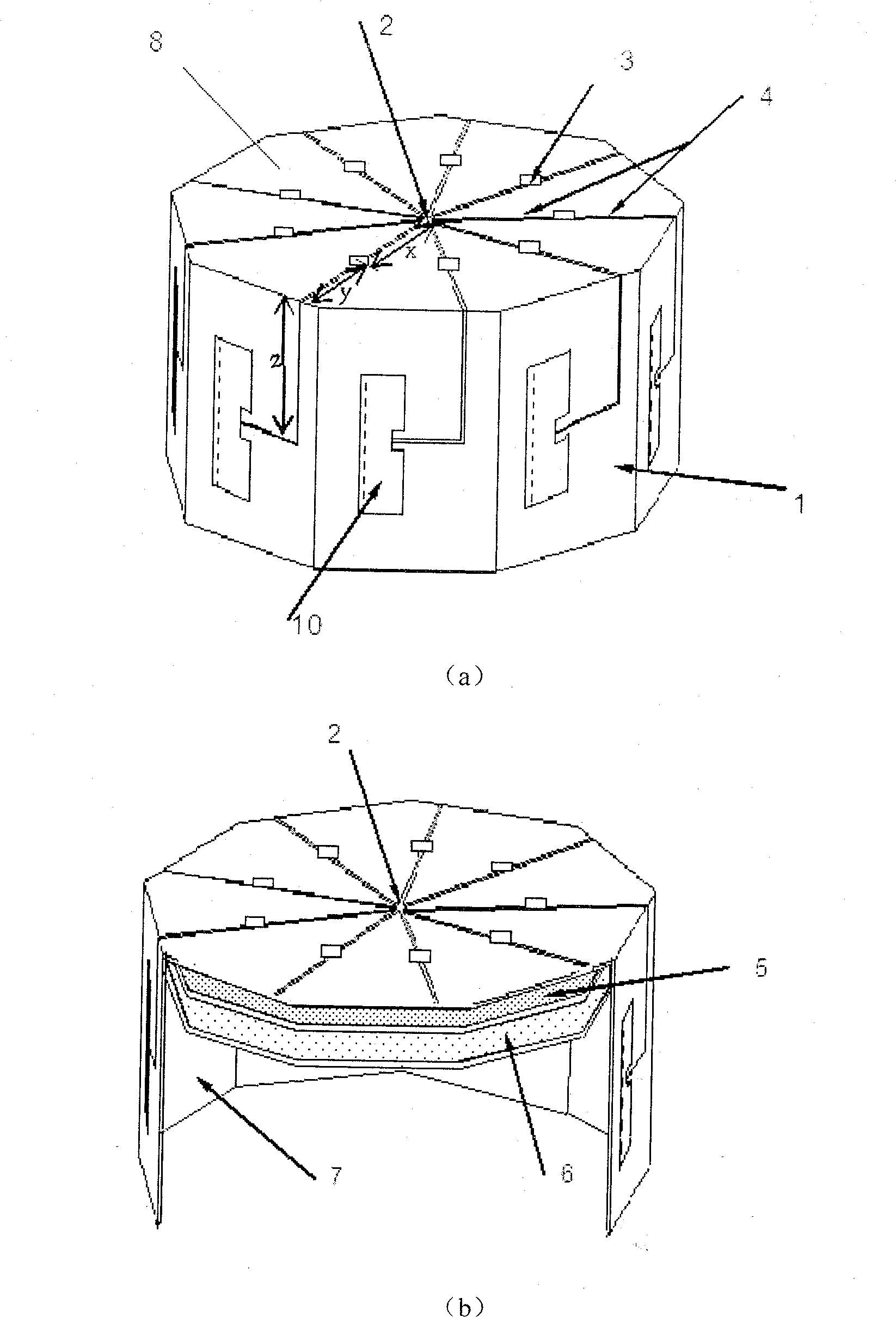
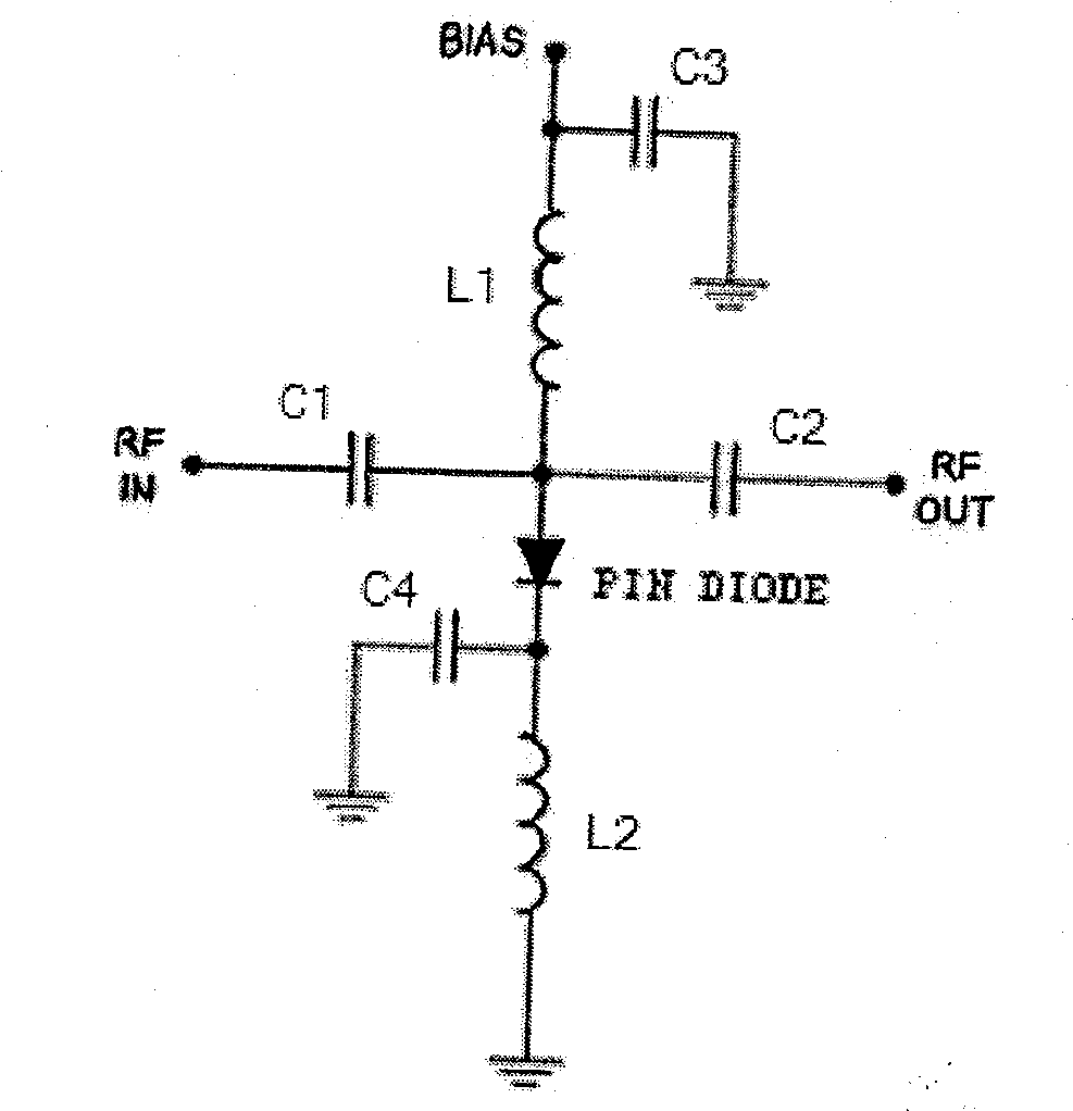
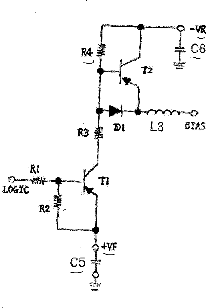
[0027] like figure 1 As shown, a specific embodiment of the positive polyhedron beam switching smart antenna device of the present invention is a positive nine prism beam switching smart antenna device, including a power distribution / combiner 2, a radio frequency switch 3, a microstrip antenna unit 10 and a feeder 4, a drive Circuit and logic control circuit; the shape of the antenna device is a regular nine prism, the microstrip antenna unit 10 is arranged on each cylindrical surface 1 of the regular nine prism, and the power distribution / combiner 2 is arranged on the vertical regular nine prism The center of the regular nonagonal end face 8 of the surface 10, the radio frequency switch 3 is evenly distributed on the periphery of the regular nonagonal end face 8 center, and is connected with the power distribution / combiner 2 and the microstri...


PUM


Abstract

The invention relates to a positive polyhedral wave beam switch intelligent antenna, which is symmetry, wherein it comprises a power distributor / coupler, a radio switch, a micro antenna unit, a feedback wire, a driving circuit and a logic control circuit; said antenna is one positive polyhedral; the micro antenna un it is on each surface of positive polyhedral;the power distributor / coupler is at the end center of positive polyhedral; the radio switch is around the center of end surface of polyhedral, to connect the power distributor / coupler and micro antenna via feedback wires; the number of radio switches is same as the number of micro antennas; the driving circuit and the logic control circuit are at the inner chamber of antenna array. The invention has low insert consumption and low cost.

Description

technical field [0001] The invention relates to an antenna device for a wireless communication system, in particular to a smart antenna device for beam switching. Background technique [0002] The smart antenna system gets its name because it contains many advanced signal processing techniques, which are essentially different from traditional antenna systems. A smart antenna system refers to an antenna system with "dynamic" and "intelligent" characteristics formed by the organic combination of multiple antennas and space-time signal processing algorithms. On the one hand, the system can use airspace diversity or adaptive beamforming technology to effectively suppress interference and increase the signal-to-interference ratio, thereby doubling the system capacity; on the other hand, it can use diversity technology to combat multipath fading and improve the reliability of the communication system At the same time, the diversity gain or array gain can be used to improve the ne...

Claims


Application Information

Patent Timeline
Patent Type & Authority Patents(China)
IPC IPC(8): H04B7/04H04B7/26
Inventor 殷勤业蒋延生孟玉吉王毅王慧明张莹
Owner XI AN JIAOTONG UNIV
Learn More