
Intelligent Power Control Circuit

A control circuit and intelligent power technology, applied in the field of electronics, can solve the problems of increasing the on-duty ratio of the power tube, increasing the average current of the LED, serious heating of the power tube, etc., to reduce power consumption, limit the temperature rise, and have a simple structure. Effect

Active Publication Date: 2017-04-12
CRM ICBG (WUXI) CO LTD
View PDF3 Cites 0 Cited by
  • Summary
  • Abstract
  • Description
  • Claims
  • Application Information

AI Technical Summary

Problems solved by technology

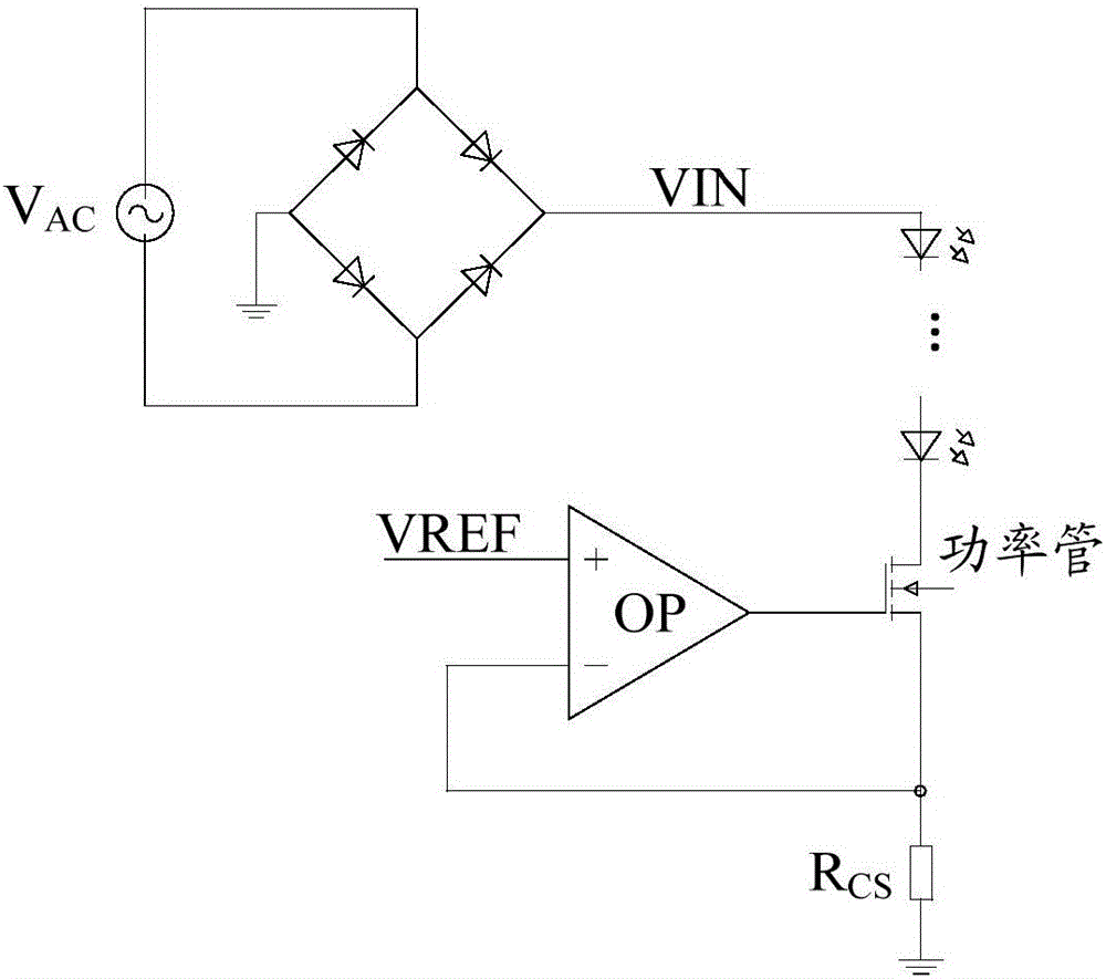
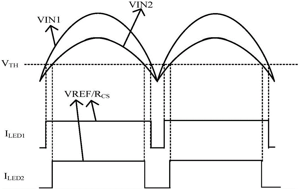
[0009] (1) In the linear constant current LED drive circuit of the prior art, as the input AC voltage increases, the conduction duty cycle of the power tube will increase, and the average LED current will increase, which is linearly adjusted within a wide input voltage range relatively low rate
[0010] (2) As the input voltage rises, the heat of the power tube is relatively serious, and the integrated over-temperature protection circuit or intelligent temperature control circuit inside the circuit is also difficult to meet the demand for 300V input high voltage in the Indian market.
[0011] (3) The two methods of over-temperature protection circuit and intelligent temperature control circuit are to take measures to reduce the temperature rise of the chip after the temperature rises, which will increase the heat dissipation cost

Method used


Image

  • Intelligent Power Control Circuit
  • Intelligent Power Control Circuit
  • Intelligent Power Control Circuit

Examples


Embodiment Construction

[0033] In order to describe the technical content of the present invention more clearly, further description will be given below in conjunction with specific embodiments.

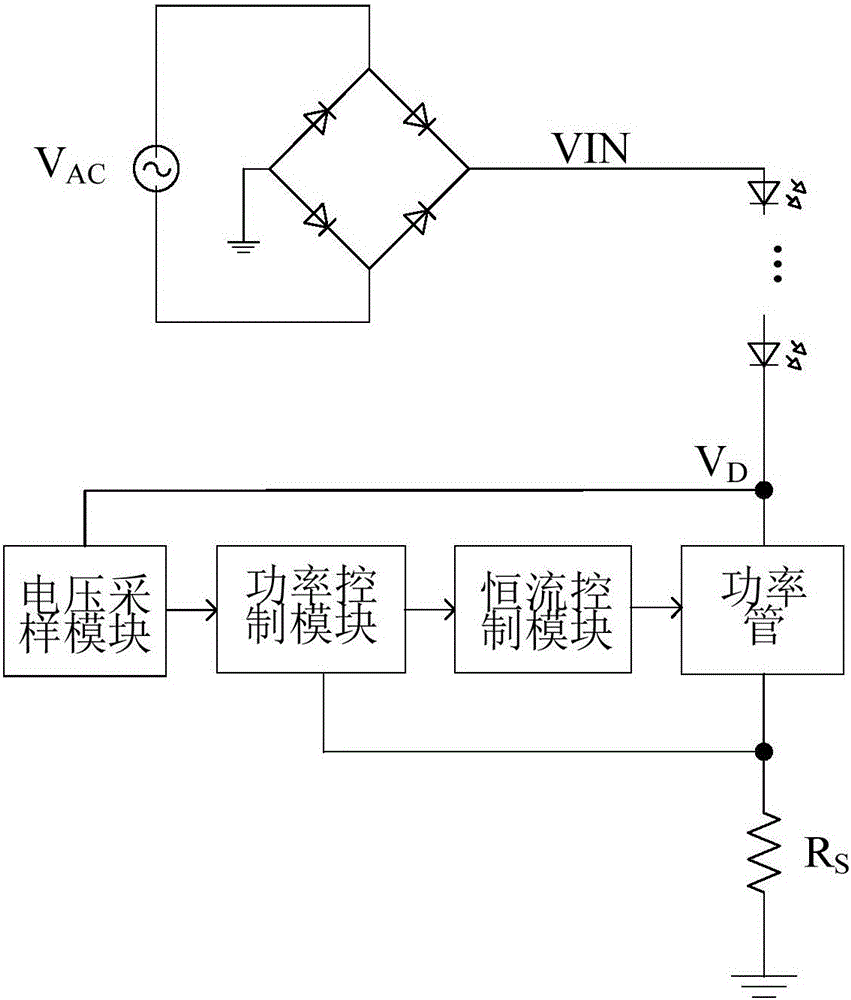
[0034] see Figure 3 to Figure 4 As shown, the intelligent power control circuit of the present invention includes a voltage sampling module, a power control module and a constant current control module; the input end of the voltage sampling module is connected to the first end of the power tube, and the voltage sampling module The output end is connected to the input end of the power control module, the output end of the power control module is connected to the input end of the constant current control module, and the output end of the constant current control module is connected to the The third end of the power tube mentioned above is connected.

[0035] where the input voltage V AC After distillation and filtering to obtain a half-wave, VIN is obtained. The voltage VIN is input to the LED lamp, and t...


PUM


Abstract

The invention relates to an intelligent power control circuit which comprises a voltage sampling module, a power control module and a constant-current control module. An input end of the voltage sampling module is connected with a first end of a power tube, an output end of the voltage sampling module is connected with an input end of the power control module, an output end of the power control module is connected with an input end of the constant-current control module, an output end of the constant-current control module is connected with a third end of the power tube, the voltage sampling module adopts a resistance sampling circuit, the power control module adopts a current mirror circuit, and the constant-current control module adopts a computing comparison circuit. In application of the intelligent power control circuit, the input voltage is detected at the beginning of running of the power tube to reduce power consumption of a driver and limit temperature rise of the power tube so as to reduce cooling cost of the driver and an LED lamp; in addition, the intelligent power control circuit is simple in structure and wide in application range.

Description

technical field [0001] The present invention relates to the field of electronic technology, in particular to circuit design, in particular to an intelligent power control circuit. Background technique [0002] In the LED drive circuit, the current flowing through the power tube is relatively large, and the voltage applied to both ends of the power tube increases with the increase of the input voltage, and the heat generation of the power tube will be more obvious. The temperature will continue to rise, and the life of the LED will be reduced if the power is too high. Therefore, the input voltage of the common linear constant current drive circuit will not be very high, and it is difficult to meet the demand for 300V high voltage input similar to the Indian market. In addition, the linear constant current The driver has relatively low linear regulation over a wide input voltage range. [0003] see figure 1 As shown, it is a linear constant current LED driving circuit in the...

Claims


Application Information

Patent Timeline
Patent Type & Authority Patents(China)
IPC IPC(8): H05B37/02
CPCY02B20/40
Inventor 刘玉芳丁增伟罗先才徐栋夏虎
Owner CRM ICBG (WUXI) CO LTD
Learn More