
Method for finding shear rate of fluid, and program and device for same

A technology of shear rate and measurement method, which is applied in the field of calculating the shear rate of fluids, its procedures and devices, and can solve problems such as the inability to determine the shear rate

Inactive Publication Date: 2014-12-24
A&D CO LTD
View PDF11 Cites 4 Cited by
  • Summary
  • Abstract
  • Description
  • Claims
  • Application Information

AI Technical Summary

Problems solved by technology

Therefore, it is recognized as a measurement method that cannot determine the shear rate (see Patent Document 1 and Patent Document 2 for the tuning fork vibration method, and non-patent document 1 for the rotational vibration method)

Method used


Image

  • Method for finding shear rate of fluid, and program and device for same
  • Method for finding shear rate of fluid, and program and device for same
  • Method for finding shear rate of fluid, and program and device for same

Examples


Embodiment 1

[0075] As the sample solution 9, 45 ml of ion-exchanged water (under a constant condition of 25[° C.]) which is a Newtonian fluid was used. The measurement conditions are: the measurement time is 11 minutes, the lower limit value of the amplitude is 0.2mm, and the upper limit value is 1.2mm, the variation of the time distribution of the amplitude is Δ0.2mm / min, and the amplitude decreases and reciprocates after rising. In addition, since the viscosity of ion-exchanged water (25 [degreeC]) is known (in accordance with JIS Z8803), the value was input and measured. exist Figure 7 The center represents a curve in which the shear rate [1 / s] is plotted on the horizontal axis, the viscosity [mPa·s] is plotted on the vertical axis, and the resulting shear rate is plotted.

Embodiment 2

[0077] As the sample solution 9, 45 ml of a non-Newtonian fluid moisturizing cream for skin (under constant conditions of 25[° C.]) was used. In the measurement, the measurement time is 15 minutes, the lower limit value of the amplitude is 0.07mm, and the upper limit value of the amplitude is 1.2mm, so that the amplitude change amount is 0.07, 0.1, 0.2, 0.4, 0.6, 0.8, 1.0, 1.2mm every minute. The amplitude rises and then falls, reciprocating. Viscosity After the start of the measurement, the viscosity value after 1 minute of each amplitude was acquired. exist Figure 8 The center represents a curve in which the shear rate [1 / s] is plotted on the horizontal axis, the viscosity [mPa·s] is plotted on the vertical axis, and the resulting shear rate is plotted.

Embodiment 3

[0079] As the sample solution 9, 45 ml of standard solutions JS20, JS200, JS2000, and JS14000 (all under constant conditions of 25[° C.]) were used next as ion-exchanged water of Newtonian fluid. The measurement conditions were performed in the same manner as in Example 1. In addition, since all viscosity is known (in accordance with JIS Z8803), the value was input and measured. exist Figure 9 The middle represents a curve in which the viscosity [mPa·s] is plotted on the horizontal axis, the shear rate [1 / s] is plotted on the vertical axis, and the resulting shear rate is plotted for each liquid.

[0080] From the above, in the method for obtaining the shear rate of the present invention, the shear rate is obtained from the driving force F (driving current I) as an actual measurement value and the viscosity η based on the measurement, so it is possible to obtain The shear rate reflecting the dynamics of the fluid based on the geometric shape of the device can contribute to ...


PUM


Abstract

To propose a new method for finding the shear rate of a fluid and to provide a program and device for the same. A method to find shear rate with a tuning-fork vibration viscometer that calculates the viscosity of the sample fluid (9) by vibrating a pair of oscillators (1, 1) that are submerged in the sample fluid (9) by way of an electromagnetic driver (2) comprising a coil (2b), causing a driving current to flow in the coil (2b) so that the amplitude of the oscillator (1) is the set amplitude value, and measuring the driving current, comprises: a viscosity acquisition step (S1) of acquiring the viscosity ([eta]) of a sample fluid (9); a driving force acquisition step (S2) of finding, from the driving current (I), a driving force (F) in the center of a wetted portion of the oscillator; and a shear stress acquisition step (S3) of finding, from the driving force (F) and the wetted area (A) of the oscillator, the shear stress (S) working on the sample fluid; wherein the shear rate (D) is found from the ratio of the shear stress (S) and the viscosity ([eta]) (S4).

Description

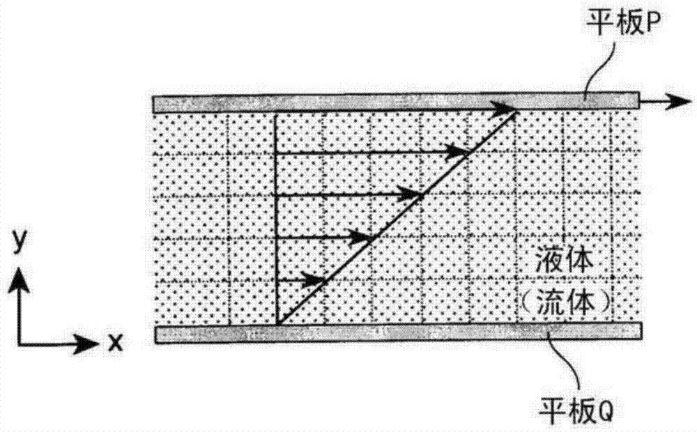
technical field [0001] The present invention relates to a method for obtaining a shear rate for evaluating a fluid's physical properties, and more particularly to a method for calculating a fluid's shear rate, its program, and an apparatus. Background technique [0002] known as figure 1 As shown, in the fluid space of orthogonal coordinates, two parallel plates P and Q are arranged in the x direction, and the velocity gradient when the plate P is fixed and the plate Q moves at a certain speed in the x direction is used, that is, the shear The shear rate D and the shear stress S, which is the frictional force acting per unit area on a plane parallel to the flow direction between the flat plates PQ due to the difference in the speed, are expressed by equation (1) as An important element of physical properties is viscosity η. Equation (1) means that the viscosity η of the fluid is obtained as the ratio of the shear stress S generated in the fluid to the shear rate D. [000...

Claims


Application Information

Patent Timeline
Patent Type & Authority Applications(China)
IPC IPC(8): G01N11/10
CPCG01N11/00G01N11/14G01N11/16G01N2011/0026
Inventor 出云直人菅野将弘
Owner A&D CO LTD
Learn More