Wave soldering device and its nozzle

A technology of wave soldering and nozzle openings, which is applied in the field of wave soldering devices and nozzles, can solve the problems of a large amount of high-temperature exhaust gas, increase cleaning costs, and material waste, and achieve the effects of reducing welding slag, saving equipment costs and energy, and being easy to manufacture

Active Publication Date: 2018-03-06
레노보인터내셔널리미티드
View PDF13 Cites 0 Cited by
  • Summary
  • Abstract
  • Description
  • Claims
  • Application Information

AI Technical Summary

Problems solved by technology

The formation of welding slag causes a great waste of material and increases the cost of cleaning
[0007] In addition, during the wave soldering process, a large amount of high-temperature exhaust gas will be generated when the high-temperature molten solder contacts the circuit board, resulting in energy loss

Method used


Image

  • Wave soldering device and its nozzle
  • Wave soldering device and its nozzle
  • Wave soldering device and its nozzle

Examples


Embodiment Construction

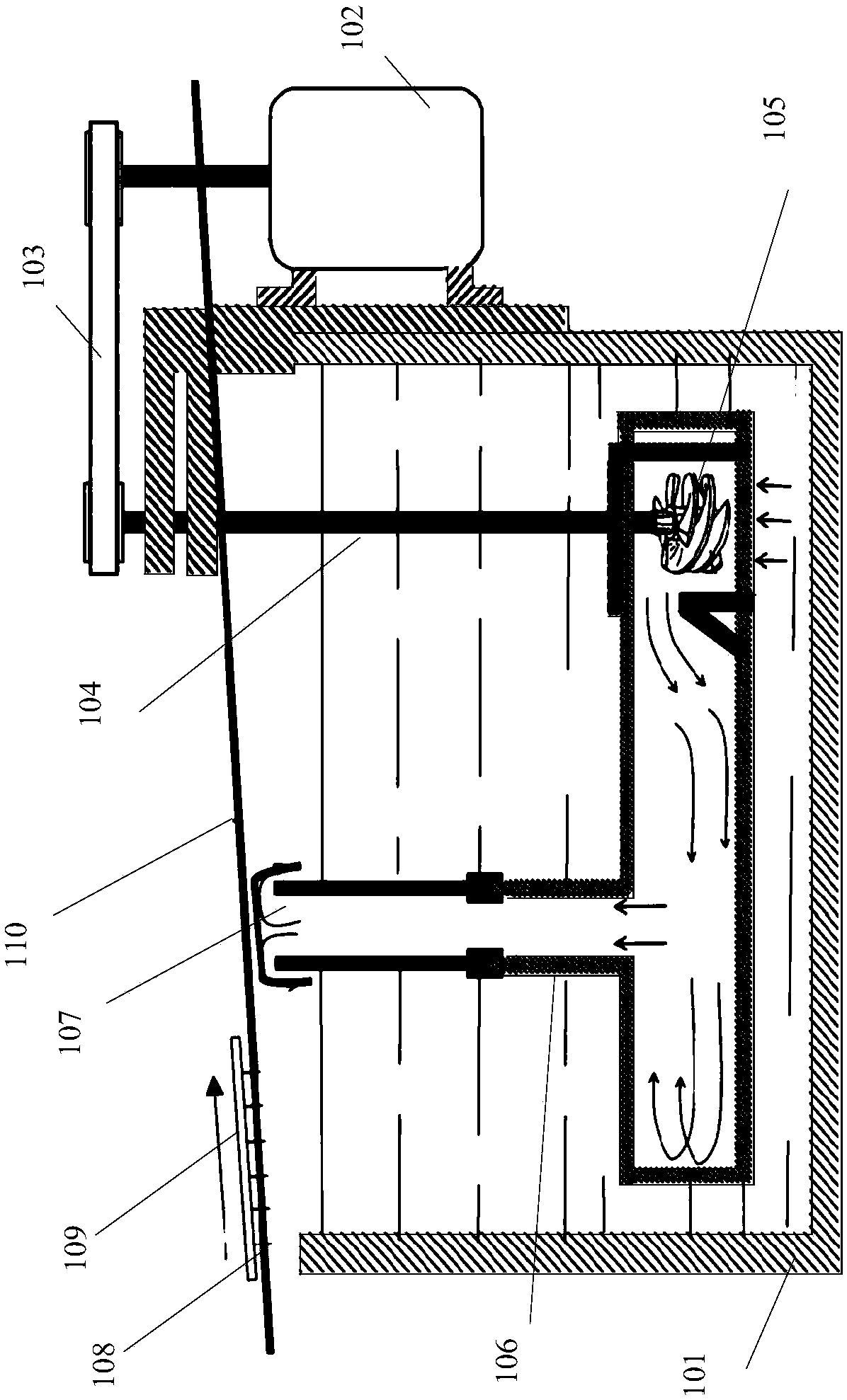
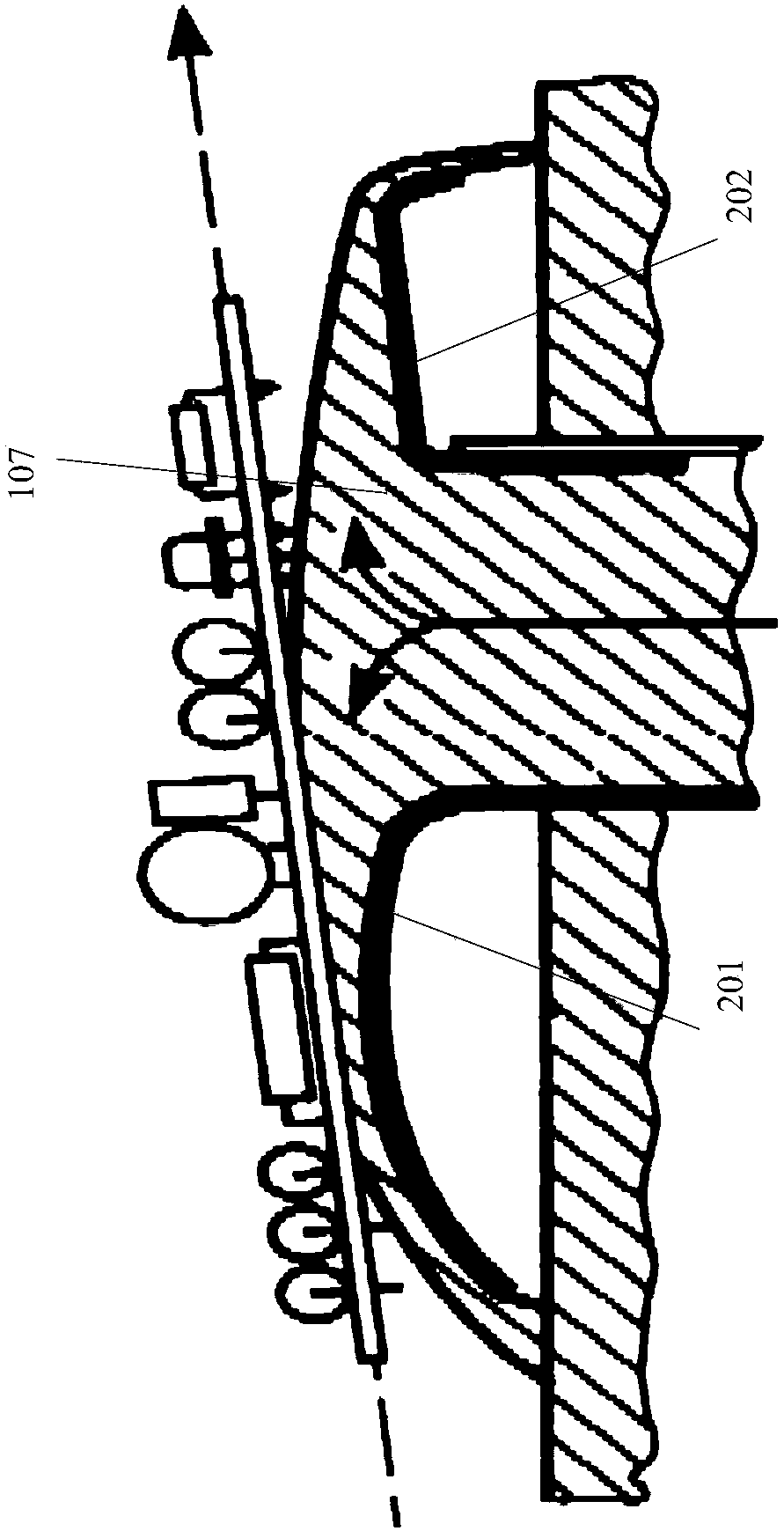
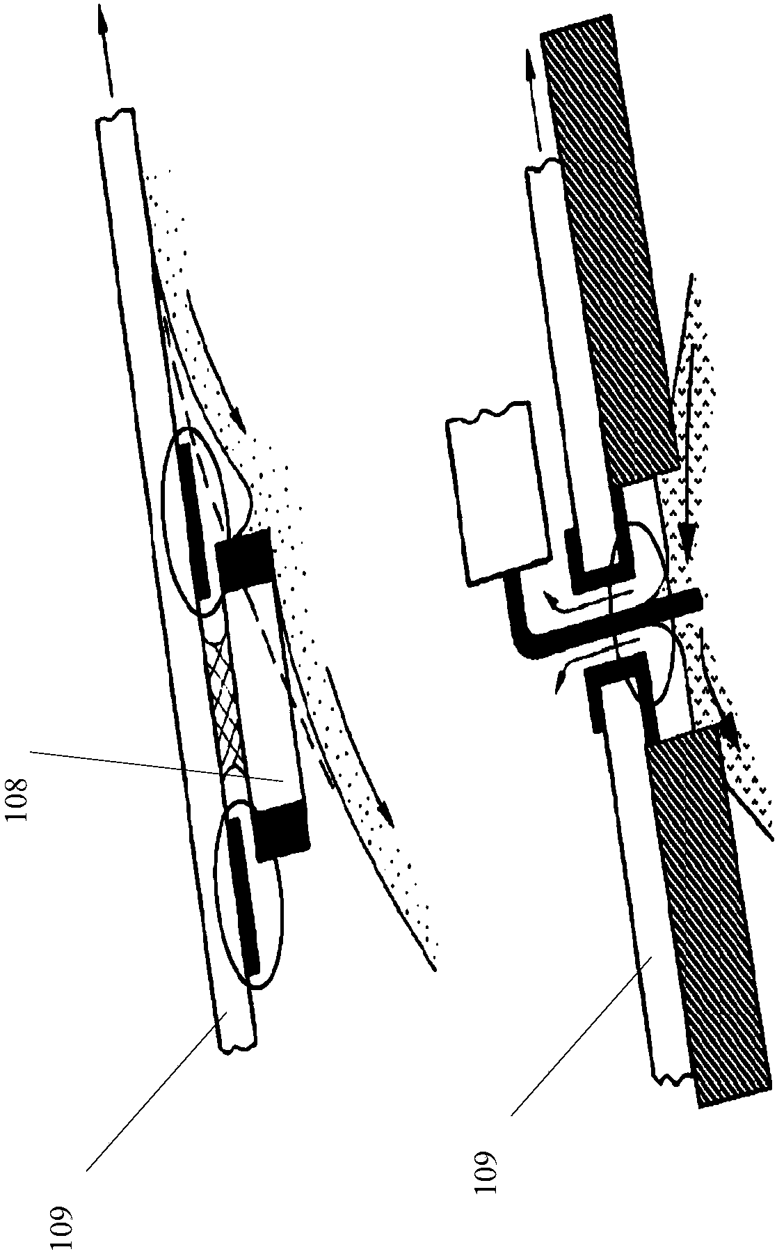
[0024] Now refer to Figure 5 , which shows a view of a wave soldering apparatus 500 according to an embodiment of the present invention. As shown in the figure, the wave soldering apparatus 500 includes: a solder pool 501, configured to store molten solder; a conveying device 502, configured to transport a circuit board to be soldered close to the solder pool; a pump device 503, configured to The molten solder in the solder pool is transported to the nozzle device through the delivery pipeline; the nozzle device 504 is configured to spray the molten solder to the circuit board close to the solder pool, wherein the nozzle device 504 includes at least one pair of adjacent branch The nozzle openings, the split nozzle openings are configured to spray the melted solder towards the middle direction between the split nozzle openings.

[0025] The solder pool 501 may be any existing or newly developed solder pool for wave soldering, for example, a solder pool with a cover according t...


PUM


Abstract

A device for wave soldering is disclosed, comprising: a nozzle device configured to eject molten solder onto a circuit board adjacent to a solder pool, wherein the nozzle device includes at least one pair of adjacent sub-nozzle openings, the The halved nozzle openings are configured to spray molten solder toward the middle direction between the halved nozzle openings.

Description

technical field [0001] The invention relates to wave soldering, in particular to a wave soldering device and a nozzle thereof. Background technique [0002] Wave soldering is a soldering technique widely used in the printed circuit board production industry. This technology uses a solder pool to store molten solder; the molten solder is pumped to the nozzle and ejected from the nozzle to form a solder wave; the circuit board with the components inserted passes through the solder wave and contacts it. The molten solder adheres to the exposed metal parts of the board (that is, the parts not protected by a mask), creating a reliable mechanical and electrical connection on the board. [0003] FIG. 1 shows a schematic diagram of a typical existing wave soldering equipment 100 . As shown in the figure, molten solder (for example, solder such as lead-tin alloy) is stored in the solder pool 101 . The motor 102 of the pump device drives the rotating shaft 104 to rotate through the...

Claims


Application Information

Patent Timeline
Patent Type & Authority Patents(China)
IPC IPC(8): B23K3/08B23K3/06B23K3/00H05K3/34
CPCB23K3/0653B23K3/08
Inventor 凌理王春蒲柯张伟锋
Owner 레노보인터내셔널리미티드
Why Eureka
Try Eureka