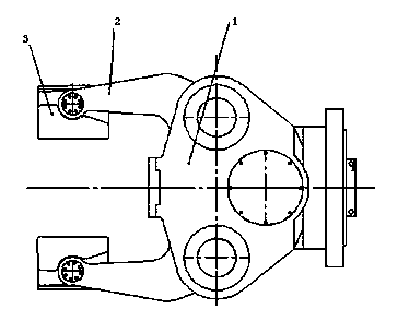
Clamp structure of forging system efficient overloaded operation robot
A kind of working robot and high-efficiency technology, applied in chucks, manipulators, manufacturing tools, etc., can solve problems such as user troubles, and achieve the effect of compact structure, expanded size range, and small overall size
Inactive Publication Date: 2014-12-31
江苏一重数控机床有限公司
View PDF0 Cites 2 Cited by
- Summary
- Abstract
- Description
- Claims
- Application Information
AI Technical Summary
Problems solved by technology
[0002] As a clamping mechanism, clamps have many requirements for it, such as clamping reliability, compact structure, and labor-saving use, etc., which are all important factors that should be considered; and the existing clamps are generally Can not have the above characteristics at the same time, bring certain troubles to users
Method used
View moreImage
Smart ImageViewing Examples
Examples
Embodiment Construction
[0011] The present invention includes a housing 1, a jaw 2 and a chuck 3, the chuck 3 is connected to the housing 1 through the jaw 2, the jaw 2 has an L-shaped structure, and the cross arm connected to the housing 1 is short For the trailing arm connected to chuck 3.
[0012] The chuck 2 adopts a concave V-shaped structure.
Login to View More PUM
 Abstract
The invention relates to a clamp structure of a forging system efficient overloaded operation robot. The clamp structure comprises a shell body, clamping jaws and clamping heads, wherein the clamping heads are connected with the shell body through the clamping jaws, the clamping jaws are respectively of an L-shaped structure, and a transverse arm, connected with the shell body, of each clamping jaw is shorter than a longitudinal arm, connected with the corresponding clamping head, of the clamping jaw. The clamp structure has the advantages that a double-L-shaped mechanism is adopted for the rotating end portion of each clamping jaw, and therefore effective space inside the shell body of the clamp structure is fully used, and more than 95% of the inner space is used; a short lever type is adopted for the clamp structure so that back arms of the clamping jaws are shorter than front arms of the clamping jaws, and therefore the stroke of each clamping jaw is short, the structure is compact, and the size is small; the clamping heads with staggered type middle-concave V-shaped jaws are adopted, the two jaws can be staggered with each other when the staggered type clamping heads are closed, and therefore the range of sizes of forge pieces clamped by the pair of jaws is enlarged; the middle-concave V-shaped jaws can effectively prevent looseness compared with linear jaws.
Description
technical field [0001] The invention relates to a clamp structure of a high-efficiency heavy-duty operation robot for a forging system, belonging to the technical field of clamping mechanisms. Background technique [0002] As a clamping mechanism, clamps have many requirements for it, such as clamping reliability, compact structure, and labor-saving use, etc., which are all important factors that should be considered; and the existing clamps are generally Can not have the above characteristics concurrently, brings certain puzzlement to the user. Contents of the invention [0003] The purpose of the present invention is to provide a high-efficiency heavy-duty operation robot clamp structure with good comprehensive performance for the above-mentioned defects. [0004] For this reason, the technical solution adopted by the present invention is: the present invention includes a housing, jaws and chucks, the chuck is connected to the housing through the jaws, the jaws are in a...
Claims
Login to View More Application Information
Patent Timeline
 Patent Type & Authority Applications(China)
IPC IPC(8): B25J15/08
Inventor 王愉翔王修山吕飞高峰傅新郭为忠张皖红朱红艳
Owner 江苏一重数控机床有限公司
Features
- R&D
- Intellectual Property
- Life Sciences
- Materials
- Tech Scout
- Unparalleled Data Quality
- Higher Quality Content
- 60% Fewer Hallucinations
Learn More Browse by: Latest US Patents, China's latest patents, Technical Efficacy Thesaurus, Application Domain, Technology Topic, Popular Technical Reports.
© 2025 PatSnap. All rights reserved.Legal|Privacy policy|Modern Slavery Act Transparency Statement|Sitemap|About US| Contact US: help@patsnap.com

