Supercharge Your Innovation With Domain-Expert AI Agents!

A steel crane beam single-column expansion joint structure

A crane beam and expansion joint technology, applied in building structure, construction and other directions, can solve the problem that the rigid frame cannot fully play the load-bearing role, affect the construction progress, increase the construction cost, etc., achieve reasonable stress, speed up the construction progress, save money cost effect

Active Publication Date: 2016-11-30
SHENYANG ALUMINIUM MAGNESIUM INSTITUTE
View PDF6 Cites 0 Cited by
  • Summary
  • Abstract
  • Description
  • Claims
  • Application Information

AI Technical Summary

Problems solved by technology

However, the temperature section length (expansion joint spacing) of the steel structure of the portal frame light-weight house is much longer than that of the ordinary steel structure factory building. Usually, the double rigidity is set at the expansion joint according to the temperature section length (expansion joint spacing) of the ordinary steel structure factory building. Due to the structural form of the frame, the rigid frame cannot fully exert its load-bearing role, resulting in waste of materials, increasing construction costs, affecting construction progress, and increasing investment

Method used


Image

  • A steel crane beam single-column expansion joint structure
  • A steel crane beam single-column expansion joint structure
  • A steel crane beam single-column expansion joint structure

Examples


Embodiment Construction

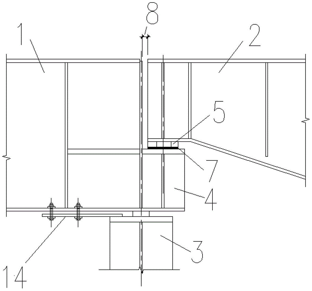
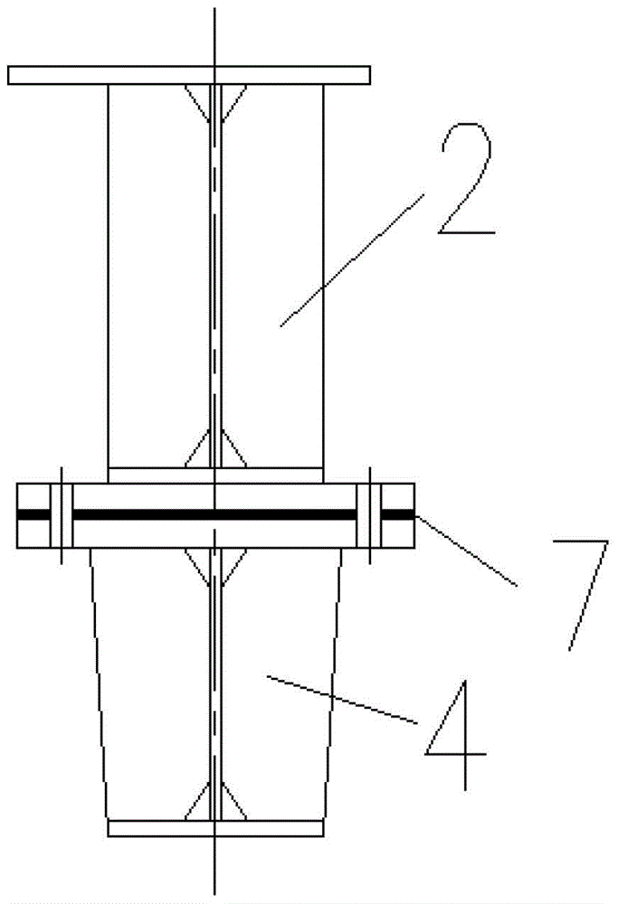
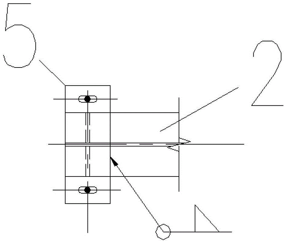
[0022] The present invention is specifically described below in conjunction with accompanying drawing, as Figure 1-Figure 7 Shown, the present invention comprises left steel crane beam 1, right steel crane beam 2, rigid frame column 3, steel corbel 4, support plate 5, connecting steel plate 9; The frame column 3 is connected with a flat support 14; the upper parts of the left steel crane beam 1 and the right steel crane beam 2 are overlapped by connecting steel plates 9; one end of the right steel crane beam 2 is a variable section, and the lower flange of the variable section end Weld a support plate 5 that opens oblong hole, be connected on the steel corbel 4 that left steel crane girder 1 stretches out with bolt by this support plate 5.

[0023] In order to reduce friction, a polytetrafluoroethylene sintered plate 7 is placed under the support plate 5 .

[0024] The expansion joint 8 between the left steel crane beam 1 and the right steel crane beam 2 has a width of 30-50...


PUM


Abstract

The invention discloses a steel crane beam single-column expansion joint structure, which is characterized in that it comprises a left steel crane beam (1), a right steel crane beam (2), a rigid frame column (3), a steel corbel (4), and a support plate (5), connecting steel plate (9); the lower flange of the crane beam (1) is connected with the rigid frame column (3) with a flat support 14; the left steel crane beam (1), the right steel crane beam (2) The upper part is lapped by connecting steel plates (9); one end of the right crane beam (2) is a variable section, and the lower flange of the variable section end is welded with a support plate (5) with an oblong hole, through which the support plate (5) be connected on the steel corbel (4) that left steel crane beam (1) stretches out with bolt. In the present invention, since the expansion joint is not used as a double rigid frame, the cost is saved and the construction progress is accelerated.

Description

technical field [0001] The invention relates to a structural form of a steel crane beam single-column expansion joint. Background technique [0002] In industrial buildings, portal frame factory buildings with cranes are very common. It has been clearly stipulated in the specification that expansion joints should be installed when the steel structure factory building exceeds a certain length. However, the temperature section length (expansion joint spacing) of the steel structure of the portal frame light-weight house is much longer than that of the ordinary steel structure factory building. Usually, the double rigidity is set at the expansion joint according to the temperature section length (expansion joint spacing) of the ordinary steel structure factory building. Due to the structural form of the frame, the rigid frame cannot fully exert its load-bearing function, resulting in waste of materials, increasing construction costs, affecting construction progress, and increa...

Claims


Application Information

Patent Timeline
Patent Type & Authority Patents(China)
IPC IPC(8): E04B1/58
Inventor 赵淑凡叶菲王春艾纯志
Owner SHENYANG ALUMINIUM MAGNESIUM INSTITUTE
Features
  • R&D
  • Intellectual Property
  • Life Sciences
  • Materials
  • Tech Scout
  • Unparalleled Data Quality
  • Higher Quality Content
  • 60% Fewer Hallucinations
Learn More