
Mitral chordae sewing machine for implanting artificial chordae through minimally invasive technology and method of mitral chordae sewing machine

An artificial chordae and mitral valve technology, applied in the field of medical devices, can solve the problem of large trauma for patients, and achieve the effect of avoiding valve leaflet pinch injury

Inactive Publication Date: 2015-06-03
SUZHOU INNOMED MEDICAL DEVICE
View PDF4 Cites 22 Cited by
  • Summary
  • Abstract
  • Description
  • Claims
  • Application Information

AI Technical Summary

Problems solved by technology

[0004] At present, for the treatment of mitral regurgitation caused by the rupture of the above-mentioned chordal tendon, the artificial chord tendon is implanted between the mitral valve leaflet and the papillary muscle through open-heart surgery, so as to prevent mitral valve leaflet prolapse. Mitral valve regurgitation caused by sagging, but this operation requires a chest open heart, which is very traumatic to the patient, and is not suitable for elderly or frail patients

Method used


Image

  • Mitral chordae sewing machine for implanting artificial chordae through minimally invasive technology and method of mitral chordae sewing machine
  • Mitral chordae sewing machine for implanting artificial chordae through minimally invasive technology and method of mitral chordae sewing machine
  • Mitral chordae sewing machine for implanting artificial chordae through minimally invasive technology and method of mitral chordae sewing machine

Examples


Embodiment Construction

[0070] The present invention will be further described below with reference to the drawings and specific embodiments, but the protection scope of the present invention is not limited to this.

[0071] In the description of the present invention, it should be understood that the terms "upper", "lower", "front", "rear", "left", "right", "top", "bottom", "inner", "outer" The orientation or positional relationship indicated by "" is based on the orientation or positional relationship shown in the drawings, and is only for the convenience of describing the present invention and simplifying the description, and does not indicate or imply that the device or element referred to must have a specific orientation and The azimuth structure and operation of, therefore cannot be understood as a limitation of the present invention.

[0072] In addition, the terms "first" and "second" are only used for descriptive purposes, and cannot be understood as indicating or implying relative importance or ...


PUM


Abstract

The invention discloses a mitral chordae sewing machine for implanting the artificial chordae through the minimally invasive technology and a method of the mitral chordae sewing machine in the field of medical apparatus and instruments. The mitral chordae sewing machine comprises a mitral forceps holder, sewing needles and a position detection device, wherein the mitral forceps holder is capable of clamping a mitral leaflet; the mitral forceps holder comprises an operating handle, a support rod and a clamping device of which the front end is opened and closed under the control of the operating handle; the number of the sewing needles is two; each sewing needle is designed to be of a barb structure, and the barb structures are used for hooking the artificial chordae; the position detection device is used for detecting the position, clamped by the mitral forceps holder, of the mitral leaflet; the mitral leaflet can be implanted into a human body through the small incision of left chest, and enters the ventriculus sinister from the apex cordis position to clamp the mitral leaflet; the sewing needles penetrate through the mitral leaflet to hook the artificial chordae, so that a liner is adhered to the mitral leaflet at one side of the atrium sinistrum, and two ends of the artificial chordae are fixed to the apex cordis position. According to the mitral chordae sewing machine and the method of the mitral chordae sewing machine disclosed by the invention, the goal that the artificial chordae is implanted through the minimally invasive technology is achieved, and patients with mitral regurgitation caused by the rupture of the mitral chordae are effectively treated.

Description

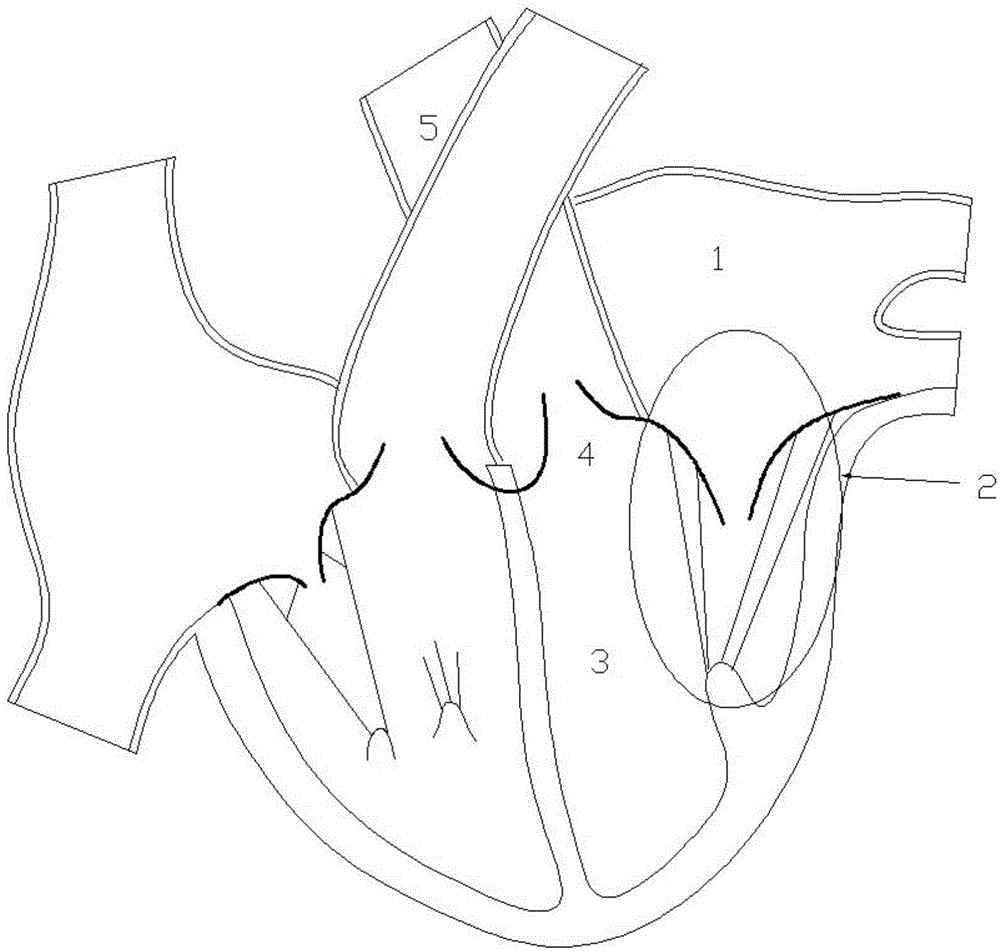
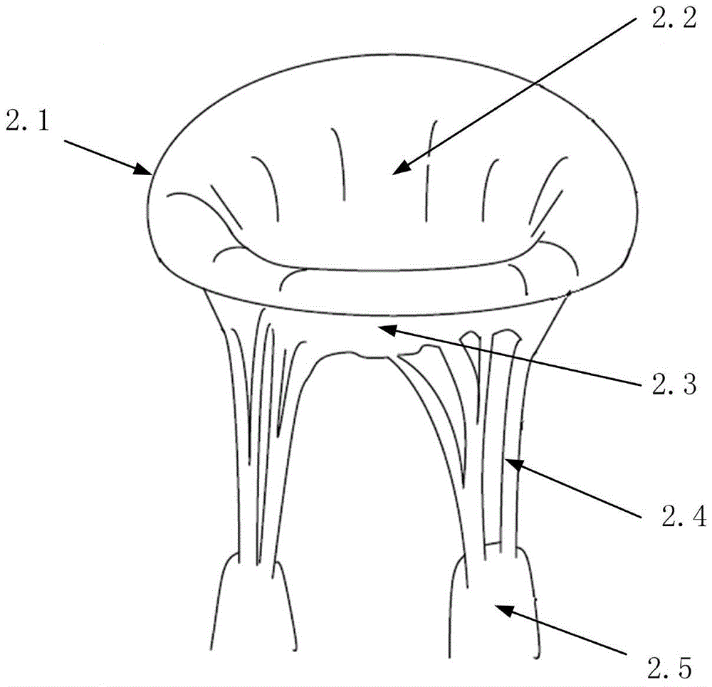
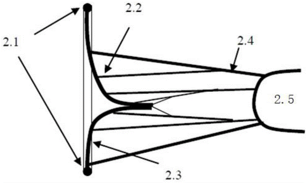
Technical field [0001] The invention belongs to the field of medical equipment, and particularly relates to a mitral valve chordal sewing machine with minimally invasive implantation of artificial chordae and a method thereof. Background technique [0002] The human heart and valves such as figure 1 As shown, the mitral valve 2 is located between the left atrium 1 and the left ventricle 3, and controls the one-way flow of blood from the left atrium 1 into the left ventricle 3. The structure of mitral valve 2 is like figure 2 As shown, the mitral valve is a complex structure consisting of annulus 2.1, anterior leaflets 2.2, posterior leaflets 2.3, chordae 2.4, papillary muscle 2.5, and the myocardium on the left ventricular wall. The anterior leaflet 2.2 and the posterior leaflet 2.3 are attached to the annulus 2.1. Annulus 2.1 is an internal tissue structure connecting the anterior valve leaflets 2.2, the posterior valve leaflets 2.3 and the left ventricular wall. The chordae ...

Claims


Application Information

Patent Timeline
Patent Type & Authority Applications(China)
IPC IPC(8): A61B17/04
CPCA61B17/0401
Inventor 贺照明荆腾
Owner SUZHOU INNOMED MEDICAL DEVICE
Learn More