Eureka AIR delivers breakthrough ideas for toughest innovation challenges, trusted by R&D personnel around the world.

Low-voltage power distribution structure cabinet

A low-voltage power distribution and bottom structure technology, applied in the mechanical field, can solve time-consuming and labor-intensive problems, and achieve the effect of meeting installation requirements, reducing volume and stabilizing structure

Inactive Publication Date: 2014-12-31
JIANGSU YINJIA GROUP
View PDF5 Cites 2 Cited by
  • Summary
  • Abstract
  • Description
  • Claims
  • Application Information

AI Technical Summary

Problems solved by technology

Now, in order to reduce the cost, each manufacturer makes the whole group of distribution cabinet busbars into 5~6 power distribution cabinets sharing a set of top main busbars that can pass through the length. During on-site installation, the busbars need to be passed through the side of the whole group of power distribution cabinets. Into the square hole on the top of the busbar room, so that the site needs a lot of space
However, when the space in the power distribution room is limited and there is no distance between the two ends of the switchgear arrangement, it is necessary to dig holes in the wall to ensure the penetration of the entire main busbar. This method is time-consuming and laborious.

Method used


Image

  • Low-voltage power distribution structure cabinet
  • Low-voltage power distribution structure cabinet
  • Low-voltage power distribution structure cabinet

Examples


Embodiment Construction

[0021] The present invention will be further explained below in conjunction with the accompanying drawings and specific embodiments. It should be understood that the following specific embodiments are only used to illustrate the present invention but not to limit the scope of the present invention.

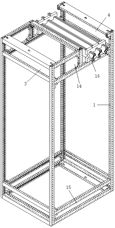
[0022] figure 1 It is a schematic diagram of the overall structure of the present invention. As can be seen from the figure, the present invention includes a bottom structure 15 and a top structure 14. The top structure 14 and the bottom structure 15 are connected and fixed by four columns 1. The top structure 14 is located vertically above the bottom structure 15. The top structure 14 includes an outlet room 3 and a main busbar room 4 , and the main busbar room 4 is used for installing the main busbar 16 .

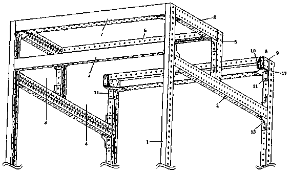
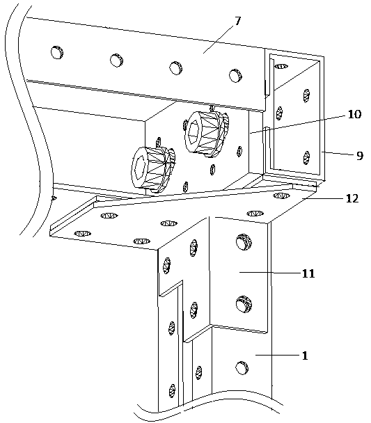
[0023] figure 2 yes figure 1 The schematic diagram of the top structure in the figure can be seen in conjunction with the two accompanying drawings. In the present invent...


PUM


Abstract

The invention relates to a low-voltage power distribution structure cabinet. The low-voltage power distribution structure cabinet comprises a bottom structure and a top structure, wherein the top structure and the bottom structure are fixedly connected through four stand columns, the top structure comprises an outgoing wire chamber and a main busbar chamber which are horizontally arranged, transverse beams are arranged around the bottoms of the outgoing wire chamber and the main busbar chamber, the transverse beams are perpendicularly fixed between adjacent stand columns, a cabinet center beam and two longitudinal beams are arranged in the middle of the outgoing wire chamber and the main busbar chamber, the bottom ends of the two longitudinal beams are perpendicularly fixed with the transverse beams, the two ends of the cabinet center beam are respectively and fixedly connected with the tops of the two longitudinal beams, top beams are respectively arranged between the tops of the stand columns of the outgoing wire chamber and the main busbar chamber, and the top beams of the outgoing wire chamber are connected with the cabinet center beam through connecting beams. The low-voltage power distribution structure cabinet has the advantages that the structure is stable and compact, the strength is high, the size is small, the demands of site installation and hoisting can be met, and the problem that a hole needs to be excavated due to a small installation space is overcome.

Description

technical field [0001] The invention relates to a low-voltage power distribution structure cabinet, which belongs to the field of machinery. Background technique [0002] The top structure of the bus bar on the top of the conventional power distribution cabinet is a square hole structure, and the bus bar runs through the top of each power distribution cabinet. The type of busbar has a single type, that is, each power distribution cabinet is equipped with a busbar, and the busbar between the power distribution cabinet and the power distribution cabinet is connected by connecting the busbar connection block. Due to the increase of the copper busbar connection block, the price of the copper busbar is high, and the power distribution cabinet The cost will increase a lot, which is uneconomical and energy-saving. Now, in order to reduce the cost, each manufacturer makes the whole group of distribution cabinet busbars into 5~6 power distribution cabinets sharing a set of top mai...

Claims


Application Information

Patent Timeline
Patent Type & Authority Applications(China)
IPC IPC(8): H02B1/01
Inventor 何俊田志新杨亮何柏群陈太祥姚建明韦红根王勇
Owner JIANGSU YINJIA GROUP
Why Eureka
Eureka Blog
Learn More