Obstruction index test method, device and system
A technology of index testing and index value, applied in wireless communication, electrical components, etc., can solve the problem of low accuracy of blocking index testing and achieve the effect of improving accuracy
- Summary
- Abstract
- Description
- Claims
- Application Information
AI Technical Summary
Problems solved by technology
Method used
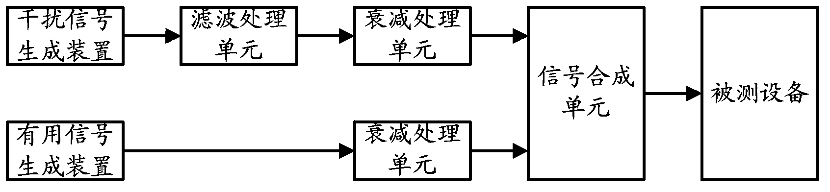
Image

Examples
Embodiment 1
[0045] In Embodiment 1 of the present invention, for the useful signal antenna, the omnidirectional first polarization antenna is used, or the omnidirectional second polarization antenna is used, or the omnidirectional first polarization antenna and the omnidirectional second polarization antenna are used successively. In the case of two kinds of polarization antennas being tested separately, the processing flow of the blocking index test is described in detail, wherein the polarization angle of the first polarization useful signal antenna is 90° different from the polarization angle of the second polarization useful signal antenna Spend.
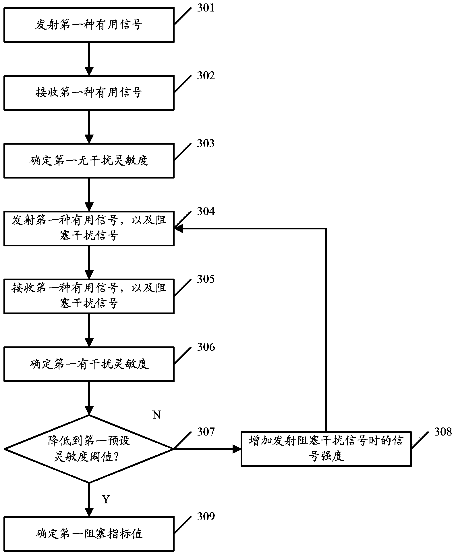
[0046] image 3 The flow chart of the blocking index test method for the useful signal antenna provided by Embodiment 1 of the present invention using the first omnidirectional polarized antenna specifically includes the following processing steps:
[0047] Step 301: Omnidirectionally transmit the first type of useful signal to the first t...
Embodiment 2
[0067] In Embodiment 2 of the present invention, the processing flow of the blocking index test is described in detail for the case where the device under test deviates from a preset position by a preset angle.
[0068] Figure 4 The flow chart of the blocking index testing method for the case where the device under test deviates from the preset position and the preset angle provided by Embodiment 2 of the present invention specifically includes the following processing steps:
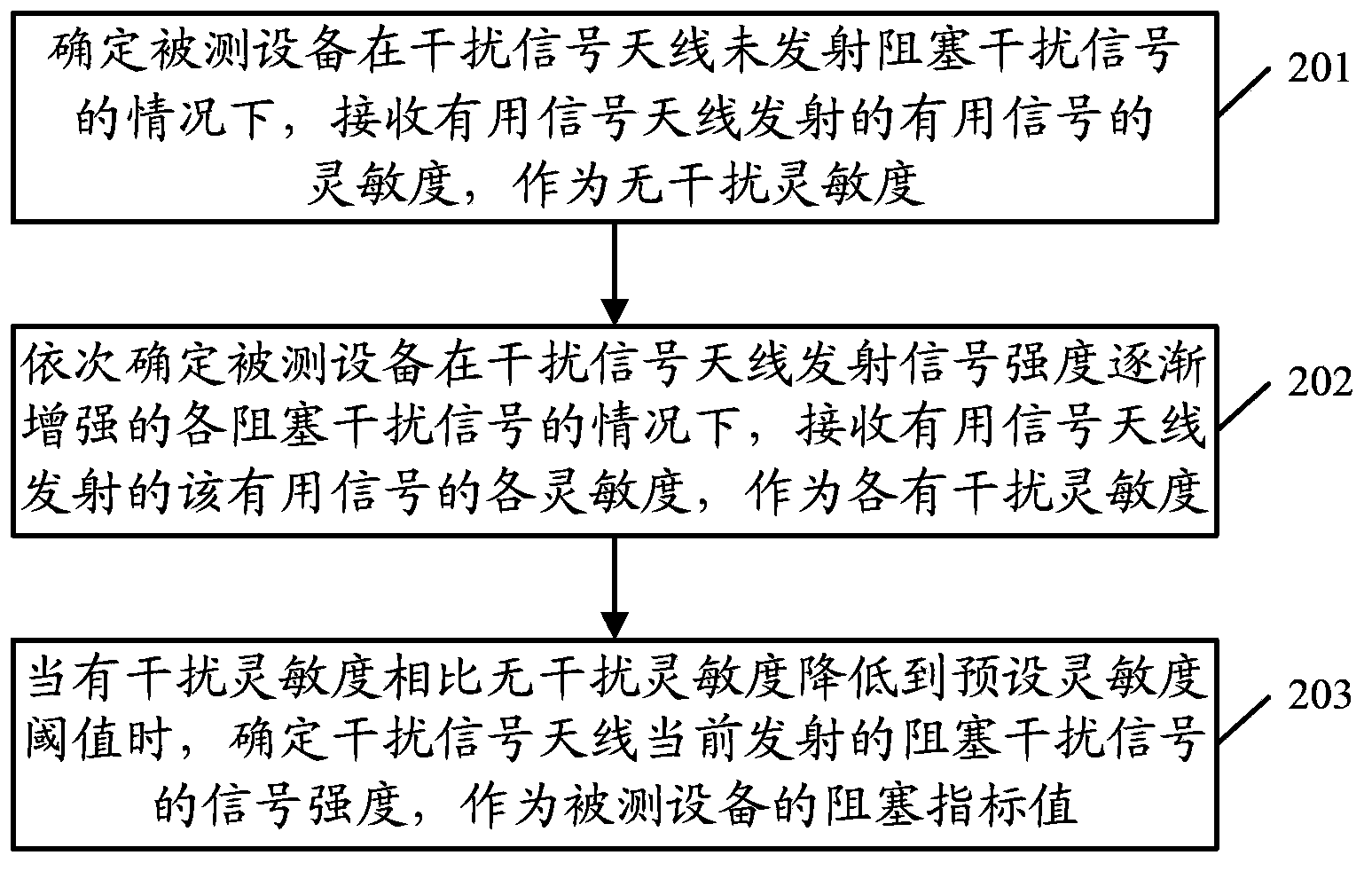
[0069] Step 401, the useful signal antenna transmits a useful signal, and the interference signal antenna does not transmit a blocking interference signal.
[0070] Further, useful signals of a specific frequency band and rate can be transmitted according to the test requirements. For example, when it is necessary to test the blocking index of the device under test receiving a useful signal of a specific frequency band and rate, the specific frequency band and rate can be transmitted in this step. rat...
Embodiment 3
[0087] In Embodiment 3 of the present invention, in the case where the useful signal antenna adopts an omnidirectional first-type polarized antenna and / or an omnidirectional second-type polarized antenna, for the case where the device under test deviates from a preset position by a preset angle, The processing flow of the blocking index test is described in detail, wherein the polarization angle of the useful signal antenna of the first type of polarization is 90 degrees different from the polarization angle of the useful signal antenna of the second type of polarization.
[0088] Figure 5 The useful signal antenna provided by Embodiment 3 of the present invention adopts the omnidirectional first-type polarized antenna, and the flow chart of the blocking index test method for the case where the device under test deviates from the preset position and the preset angle, specifically includes the following processing steps :
[0089] Step 501: Omnidirectionally transmit the firs...
PUM
 Abstract
Description
Claims
Application Information
 - R&D
- Intellectual Property
- Life Sciences
- Materials
- Tech Scout
- Unparalleled Data Quality
- Higher Quality Content
- 60% Fewer Hallucinations
Browse by: Latest US Patents, China's latest patents, Technical Efficacy Thesaurus, Application Domain, Technology Topic, Popular Technical Reports.
© 2025 PatSnap. All rights reserved.Legal|Privacy policy|Modern Slavery Act Transparency Statement|Sitemap|About US| Contact US: help@patsnap.com