Demodulation device, demodulation method, and program

A technology for demodulating equipment and channels, which is applied in the direction of demodulation, oscillation conversion angle demodulation, modulation carrier system, etc., and can solve problems such as hindering normal demodulation of input signals

Active Publication Date: 2014-12-31
SONY CORP
View PDF5 Cites 2 Cited by
  • Summary
  • Abstract
  • Description
  • Claims
  • Application Information

AI Technical Summary

Problems solved by technology

[0002] A tuner that receives a digitally modulated signal inputs the signal to a demodulation device that demodulates the digitally modulated signal, and the I channel

Method used


Image

  • Demodulation device, demodulation method, and program
  • Demodulation device, demodulation method, and program
  • Demodulation device, demodulation method, and program

Examples


Embodiment Construction

[0028] [Structure example of demodulation device]

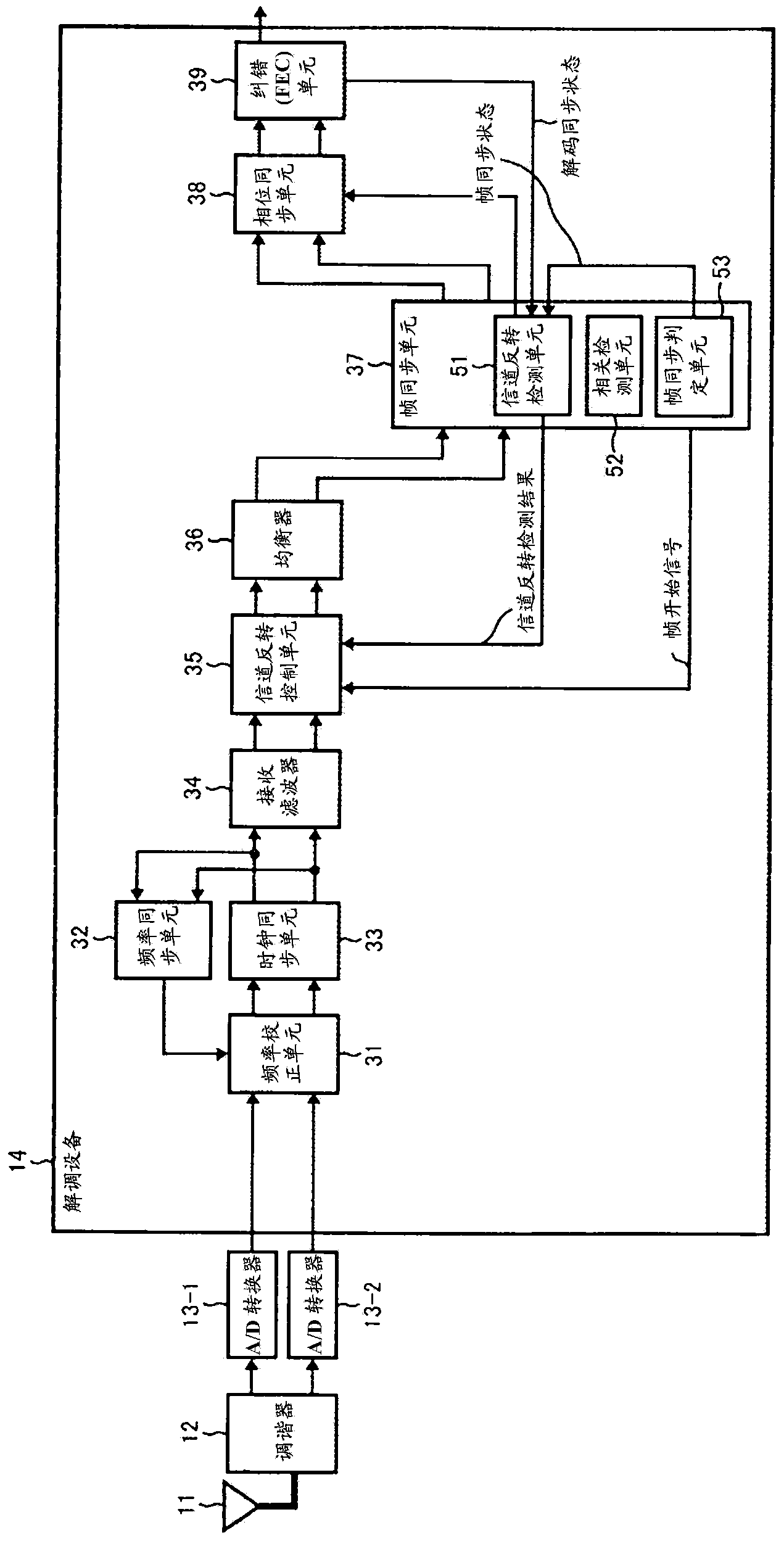
[0029] figure 1 is a block diagram illustrating an embodiment of a receiving system including a demodulation device according to the present technique. figure 1 The receiving system is a system that receives and demodulates broadcast signals (hereinafter also referred to as input signals) that conform to the DVB-S.2 standard.

[0030] The DVB-S.2 standard is a standard on top of the DVB-S standard standardized by ETSI (European Telecommunications Standards Institute). Compared with the DVB-S standard, the DVB-S.2 standard attempts to improve the frequency utilization efficiency and improve the C / N ratio (carrier noise ratio). Furthermore, as a standard, a synchronization pilot signal or a PL (Physical Layer) header for conveying transmission information of the physical layer is introduced in order to ensure synchronization performance at a low C / N ratio.

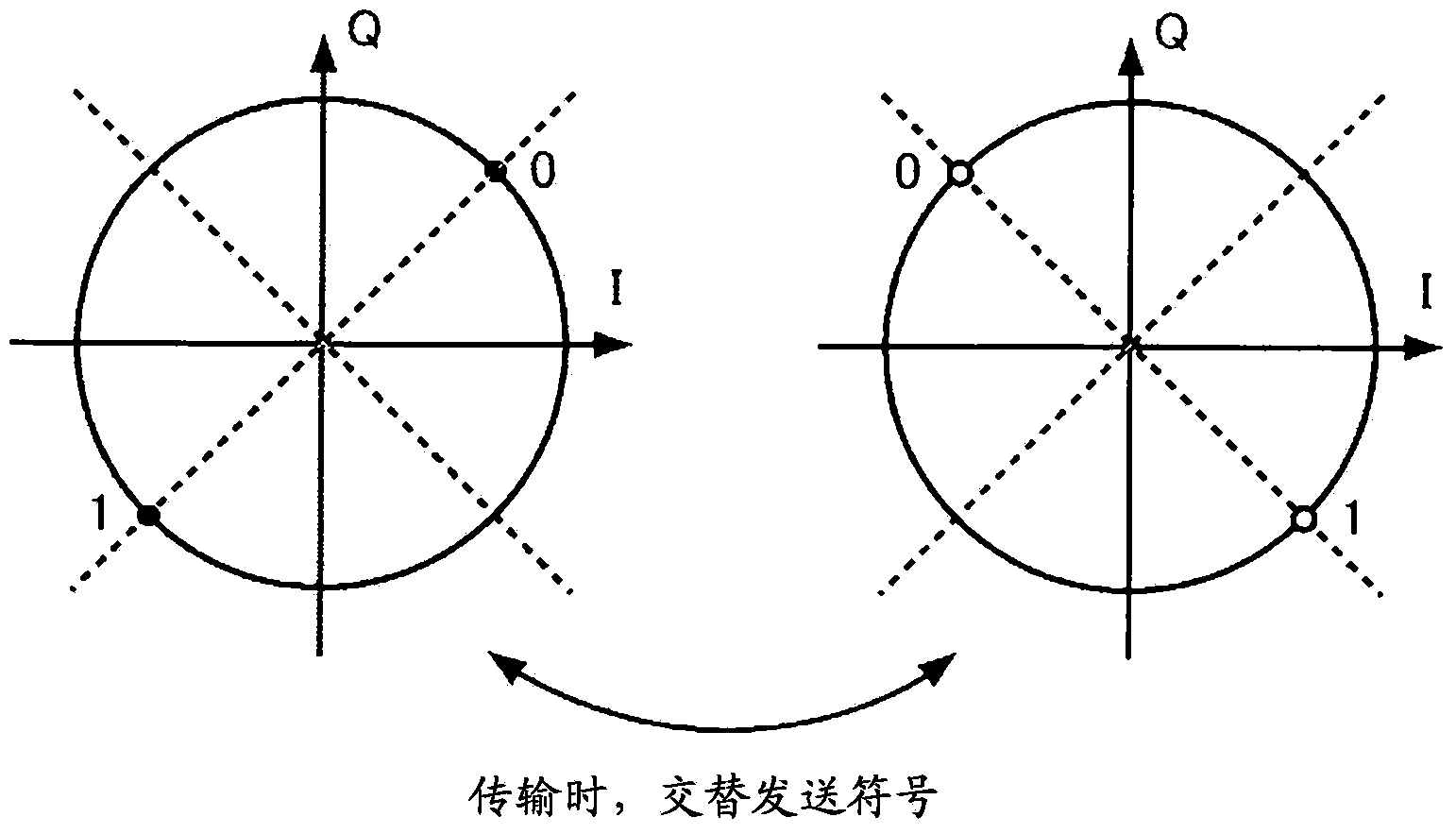
[0031] In the DVB-S.2 standard, the PL header and synchronization ...


PUM


Abstract

This invention relates to a demodulation device, demodulation method, and program which, even when an I channel signal and a Q channel signal are inputted reversed, are capable of realizing demodulation processing at a speed equivalent to the case in which no reversal has occurred. A frequency correction unit (31) establishes synchronization of the frequency and the clock on the basis of the signal of a frequency synchronization unit (32). A channel reversal detection unit (35) of a frame synchronization unit (37) detects whether there has been a reversal of the I channel signal and the Q channel signal, and supplies, as the detection result, a channel reversal detection result to the channel reversal control unit (35). The channel reversal control unit (35) swaps the I channel signal and the Q channel signal if, on the basis of the channel reversal detection result, a reversal has occurred. This technique can be applied to demodulation devices.

Description

technical field [0001] The present technology relates to a demodulation device, a demodulation method, and a program, and more specifically, to realizing a A demodulation device for demodulation processing, a demodulation method and a program. Background technique [0002] A tuner that receives a digitally modulated signal inputs the signal to a demodulation device that demodulates the digitally modulated signal, and the I channel (in-phase component) and Q channel (quadrature component) of the input signal may be inverted, thereby preventing normal operation as it is demodulates the input signal. [0003] Then, when the channel of the input signal is inverted, a technique of correcting the inversion within the demodulation device has been proposed (for example, see Patent Document 1 and Patent Document 2). In particular, in Patent Document 2, a technique for quickly detecting channel inversion is proposed. [0004] Citation list [0005] patent documents [0006] Paten...

Claims


Application Information

Patent Timeline
IPC IPC(8): H04L27/22H04L27/38
CPCH04L27/22H04L27/38H04L2027/0065H04L1/0047H03D3/007H03D2200/005
Inventor 镰田裕之平山雄一中根美沙
Owner SONY CORP
Why Eureka
Try Eureka