Rotary tillage, ridging, sowing and fertilizing all-in-one machine

An all-in-one machine and rotary tiller technology, which is applied to agricultural machinery and implements, shovels, plows, etc., can solve the problems of burning seeds, excessive equipment, mechanical dragging, etc., to reduce trouble and loss, eliminate trouble and loss, Ease of disassembly and installation

Inactive Publication Date: 2015-01-07
南阳市金海洋农机有限公司
View PDF7 Cites 21 Cited by
  • Summary
  • Abstract
  • Description
  • Claims
  • Application Information

AI Technical Summary

Problems solved by technology

For farming and sowing machinery, how to realize the organic integration of soil preparation, fertilization and sowing, and realize fast and efficient mechanized farming has always been a problem that agricultural machinery researchers continue to explore and solve. In the process, different rotary tillage and seeding machinery have emerged. For example, the disclosed patent application of CN 2593532 Y with the notification number is the disclosed rotary tillage peanut precision planter for ridges. Its weak point is that the whole machinery is too dragged, the equipment is too long, and the layout is not reasonable enough. On the one hand, the burden on the power equipment is too heavy. On the other hand, it is very inconvenient for the U-turn of the equipment
Another example is the patent application with the notification number CN 102177773 B, which discloses a multi-functional compound operation seeding machine for tillage, sowing and fertilization. Ridging and cultivating equipment covers fertilizers and seeds, which can easily cause displacement and mixed mixing of seeds and fertilizers, causing fertilizers to burn seeds, causing unnecessary troubles and losses; meanwhile, it is different from the above-mentioned rotary tillage A defect that also exists in the ridge peanut precision seeder is that the pressure wheel is used for suppression, which is easy to destroy the formed ridge

Method used


Image

  • Rotary tillage, ridging, sowing and fertilizing all-in-one machine
  • Rotary tillage, ridging, sowing and fertilizing all-in-one machine
  • Rotary tillage, ridging, sowing and fertilizing all-in-one machine

Examples


Embodiment 2

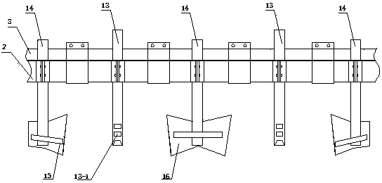
[0036] The difference between this embodiment and Embodiment 1 is that: the casing 21 and the support rod 22 are located above the cover plate 18, the casing 21 is connected with the sliding sleeve provided on the square bracket 3 through the support rod 22, and the sliding The kit is secured to the square bracket by pins, such as Figure 7 As shown, two adjacent bushings 21 are connected to the same sliding sleeve on the front side of the square bracket 3 through support rods 22, and the two bushings 21 are connected by transverse connecting rods, thereby effectively forming a stable triangular structure, Simultaneously, by being set on the transverse link, the support bar 22 that is perpendicular to the transverse link and connected with the sliding sleeve set on the rear side of the square support 3, when sowing, the support bar 22 that is connected with the front side of the square support 3 is opposite to the sowing tube. Form a pulling force, and the supporting rod 22 co...

Embodiment 3

[0038] The difference between this embodiment and the first embodiment is that the casing 21 is fixed on the cover plate 18, and has a matching arc with the seeding pipe, such as Figure 8 As shown, its arc is centered on the center line of the rotating shaft of the cover plate 18, and at the same time, the inner pipe 19 arranged on the outlet of the seeder is also an arc-shaped structure with the same radian, thereby effectively adapting to the rotation of the cover plate 18 and the outer surface of the cover plate 18. Tube 20 height adjustment. By fixing the sleeve pipe 21 on the cover plate, on the one hand, when adjusting the height of the cover plate to realize the adjustment of the ridge height, the position of the lower end of the sowing pipe and the cover plate 18 can be kept unchanged, so that the sowing depth can be kept stable, avoiding Because the adjustment of the height of the ridge causes the change of the sowing depth, on the other hand, it can effectively impr...

Embodiment 4

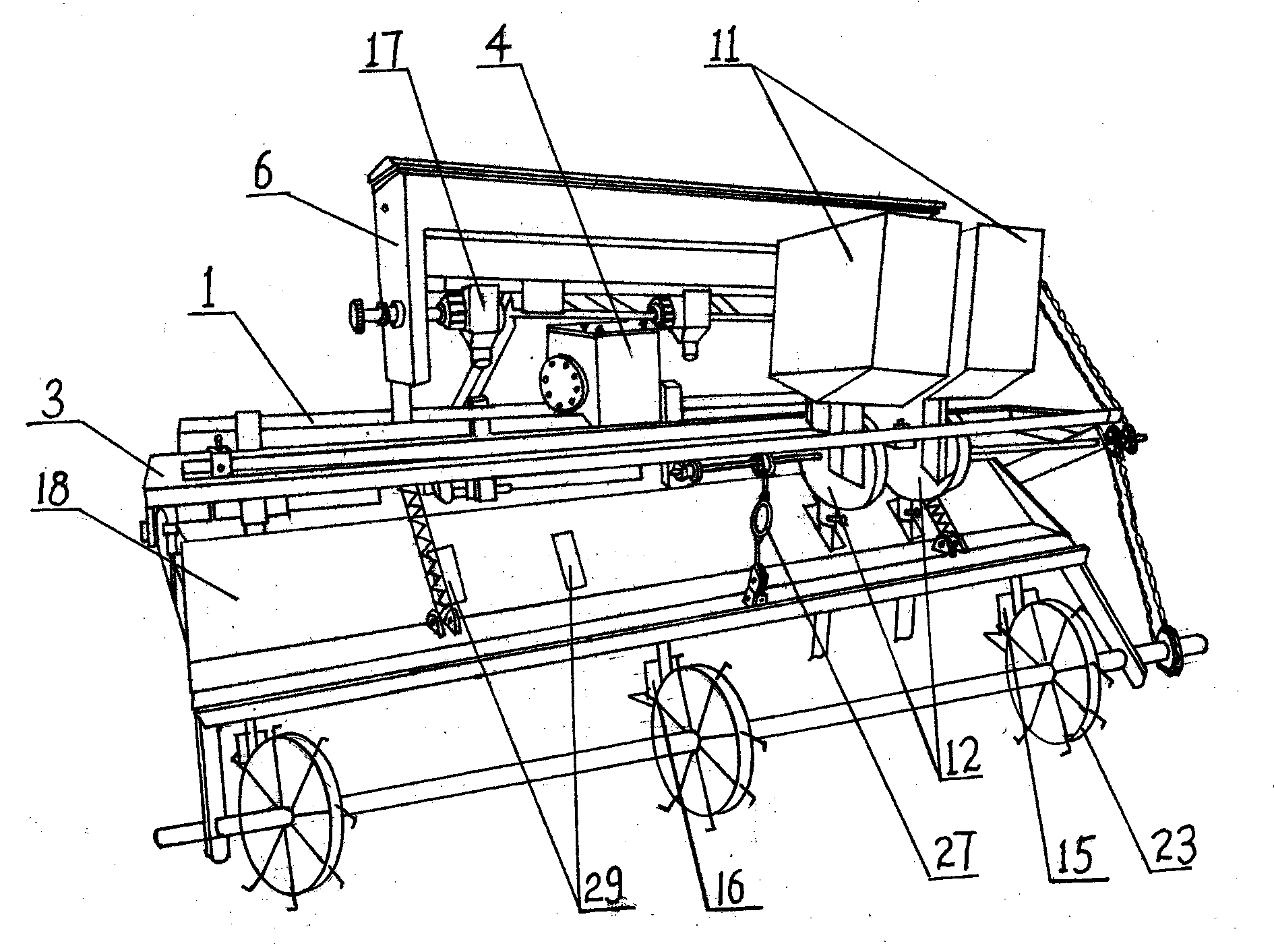
[0040] Such as Figure 9 As shown: the difference between this embodiment and the first embodiment is that the rotating shaft of the ground wheel 23 is hinged to the rear beam 2 through the connecting rod 27, and a spring pressing rod is arranged between the connecting rod 27 and the square bracket 3 28. One end of the spring pressing rod 28 is hinged with the connecting rod 27, and the other end is slidingly connected with the sliding sleeve provided on the square bracket 3, and one end of the spring inserted on the spring pressing rod 28 is against the sliding sleeve. sleeve, the other end is against the connecting rod 27 or against the limit boss arranged at the lower end of the spring pressure rod 28, and the top of the spring pressure rod 28 is inserted with a pin to prevent the spring pressure rod 28 from slipping off from the sliding sleeve. The ground wheel 23 is compressed in the groove by the spring pressure rod 28, on the one hand the overall structure of the ground...


PUM


Abstract

The invention discloses a rotary tillage, ridging, sowing and fertilizing all-in-one machine. By adopting a rack structure which is composed of a front beam, a back beam and a square bracket, arranging a fertilizer box above a gearbox, and fusing ditching, ridging, fertilizing and sowing into an integral structure, fertilization and sowing are finished in the ditching and ridging process; the all-in-one machine is not only compact and flexible, but damage from gathered soil to a fertilizing part is also avoided in the ditching and ridging process as a fertilizing leg is located in the middle of a ditcher, and stability of the soil at the fertilizing part is ensured; meanwhile, a sowing pipe is located between the fertilizing leg and the ditcher in the transverse direction, is located between side wing plates of the ditcher in the lengthways direction and is located below a soil covering plate in the vertical direction, to be short, is located at the place where soil is gathered and shaped, so that the soil is basically in a steady structure at the place, and stability of the position of a seed sown at the place can be guaranteed efficiently, row distance, plant distance and planting depth can be controlled and mastered conveniently, and precise sowing is realized.

Description

technical field [0001] The invention relates to the technical field of agricultural machinery, in particular to a rotary tillage, ridge, sowing and fertilizing integrated machine suitable for planting peanuts and soybeans. Background technique [0002] Agricultural mechanization represents advanced agricultural productivity, is an important part of agricultural modernization and plays a decisive role. With the continuous development of agricultural modernization, various tillage and sowing machinery and harvesting machinery are constantly emerging, and they are constantly moving closer to the development of joint integration. For farming and sowing machinery, how to realize the organic integration of soil preparation, fertilization and sowing, and realize fast and efficient mechanized farming has always been a problem that agricultural machinery researchers continue to explore and solve. In the process, different rotary tillage and seeding machinery have emerged. For exampl...

Claims


Application Information

Patent Timeline
Patent Type & Authority Applications(China)
IPC IPC(8): A01B49/06
Inventor 汪延忠曹璐子汪元张国松张雪玲
Owner 南阳市金海洋农机有限公司
Why Eureka
Try Eureka