Breathing machine sampling pipe water removing method and device

A technology for sampling tubes and ventilators, which is applied in the field of water removal for ventilator sampling tubes, to achieve obvious effects of water removal, ensure accuracy, and use at low cost

Pending Publication Date: 2015-01-07
NANJING SUPERSTAR MEDICAL EQUIP
View PDF3 Cites 9 Cited by
  • Summary
  • Abstract
  • Description
  • Claims
  • Application Information

AI Technical Summary

Problems solved by technology

[0004] The purpose of the present invention is to solve the problem of water removal in the sampling tube connected to the airflow tube and the pressure diffe

Method used


Image

  • Breathing machine sampling pipe water removing method and device
  • Breathing machine sampling pipe water removing method and device

Examples


Embodiment Construction

[0019] The present invention will be further described below in conjunction with embodiment:

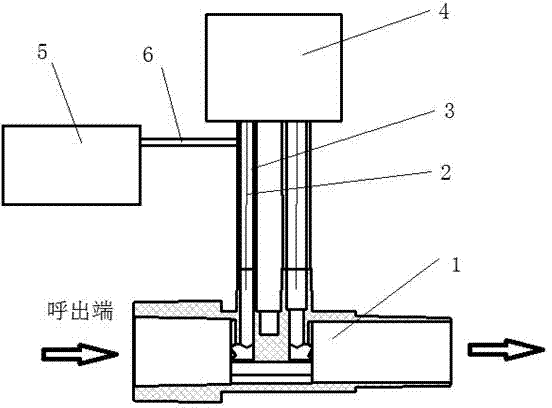
[0020] see figure 1 In the ventilator, an airflow pipe 1 through which breathing gas circulates is provided with two collection pipes 2 connected thereto, and the two pipes 2 are separated by a certain distance to collect the air pressure at two places corresponding to the airflow pipe 1 to the sensor 4. An air blowing tube 6 is arranged on the collecting tube 2 closest to the respiratory end of the air flow tube 1, and blows air to the collecting tube 2 through the blowing tube 6 with a corresponding blowing device.

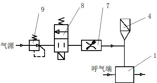
[0021] Such as figure 2 , the corresponding blowing device comprises blowing pipe 6 and blowing unit 5, and blowing unit 5 comprises decompression valve 9, the electromagnetic valve 8 and the flow regulating valve 7 of control blowing pipe 6 clearance, decompression valve 9, solenoid valve 8 and The flow regulating valve 7 is sequentially arranged on the air blowing...


PUM


Abstract

The invention discloses a breathing machine sampling pipe water removing method and device. An air blowing device is arranged on the part, close to the breathing end of a breathing machine air flow pipe, of a sampling pipe, in the breathing machine inhalation stage, the air blowing device blows air to the sampling pipe for a time. By means of the breathing machine sampling pipe water removing method and device, water vapor in the sampling pipe is removed through the simple and practical air blowing method, the problem of water vapor condensation in the breathing machine sampling pipe is quite effectively solved, the water removing air blowing device is simple, effective, low in using cost and obvious in water removing effect, the service life of a breathing machine differential pressure transducer is greatly prolonged, the accuracy of breathing parameter monitoring is ensured, and the working efficiency of medical personnel is improved.

Description

technical field [0001] The invention relates to the technical field of medical ventilator equipment, in particular to a method and device for removing water from a sampling tube of a ventilator. Background technique [0002] The differential pressure sensor (also known as differential pressure flow sensor) is a commonly used flow measurement sensor on ventilators. The differential pressure sensor measures the difference in the flow sampling tube through the thin wire probe inserted into the two sampling tubes on the airflow tube. The pressure difference measured at two points in the position, and then the flow value of the air flow in the air flow pipe is obtained. Because there is water vapor in the patient's exhaled air, water vapor often condenses in the sampling tube near the respiratory end, which will cause blockage in the sampling tube after a long time, seriously affecting the measurement results. [0003] At present, there are generally two methods to solve the pro...

Claims


Application Information

Patent Timeline
IPC IPC(8): A61M16/00
Inventor 孟保林唐雪峰
Owner NANJING SUPERSTAR MEDICAL EQUIP
Why Eureka
Try Eureka