
Sand blasting device

A technology of sandblasting cleaning device and sandblasting head, which is applied in the direction of abrasive feeding device, used abrasive processing device, abrasive jetting machine tool, etc., which can solve the problems of cleaning and other problems, and achieve space avoidance and good mobility And the effect of flexibility and concise structure

Active Publication Date: 2016-06-22
苏州华威工程技术有限公司
View PDF12 Cites 0 Cited by
  • Summary
  • Abstract
  • Description
  • Claims
  • Application Information

AI Technical Summary

Problems solved by technology

It can be seen that since the patented solution is wet sandblasting (see paragraph 0015 of the patent specification for details), the glass production line used in the service state needs to be cleaned regularly or irregularly. The cleaning of the transitional roller table of glass movement has no enlightenment for reference

Method used


Image

  • Sand blasting device
  • Sand blasting device
  • Sand blasting device

Examples


Embodiment Construction

[0022] In order to enable the examiners of the patent office, especially the public, to understand the technical essence and beneficial effects of the present invention more clearly, the applicant will describe in detail the following in the form of examples, but none of the descriptions to the examples is an explanation of the solutions of the present invention. Any equivalent transformation made according to the concept of the present invention which is merely formal but not substantive shall be regarded as the scope of the technical solution of the present invention.

[0023] In the following descriptions, all concepts involving up, down, left, right, front and rear directionality (or orientation) are for the position state of the picture being described, and the purpose is to facilitate the public Therefore, it cannot be understood as a special limitation on the technical solution provided by the present invention.

[0024] See figure 1 and figure 2 , has provided a lef...


PUM


Abstract

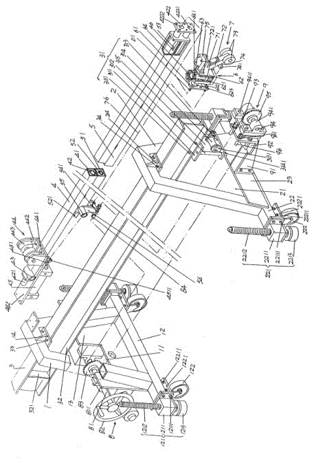
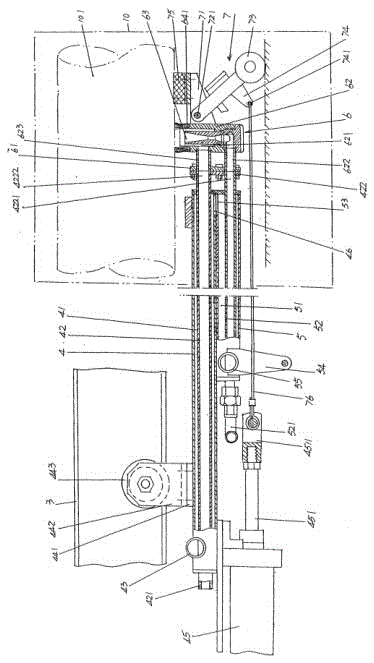
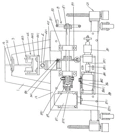
The invention discloses a sand-blast cleaning device, belonging to the technical field of cleaning equipment. The sand-blast cleaning device comprises a left frame, a right frame, a guide rail, an upper guide pipe, a lower guide pipe, a sand blasting head mechanism, a sand blasting head pressing mechanism and a guide pipe, wherein two ends of a bottom beam of the left frame are respectively provided with a left frame adjusting mechanism and a left frame walking wheel; two ends of a bottom beam of the right frame are respectively provided with a right frame adjusting mechanism and a right frame walking wheel; the left end of the guide rail is fixed with the top of the left frame, the right end of the guide rail is fixed with the top of the right frame, and a lower guide pipe guide sliding mechanism is arranged at the bottom of the right end of the guide rail; the upper guide pipe is provided with a sand return pipe in a water return cavity, a sand return pipe interface is formed by the left end of the sand return pipe, a pipe opening connecting plate is fixed by the right end of the sand return pipe, an upper guide pipe water outlet connector is arranged at the left end of the upper guide pipe, and an upper guide pipe guide sliding mechanism is arranged at the top of the upper guide pipe; the lower guide pipe is fixed with the upper guide pipe; the sand blasting head mechanism is fixed with the pipe opening connecting plate; the sand blasting head pressing mechanism is arranged on the sand blasting head mechanism; and the guide pipe is used for moving a power transmission mechanism to left and right and is arranged on the left frame. The sand-blast cleaning device disclosed by the invention has good mobility and flexibility, ensures that the sand blasting head mechanism has a relatively large working radius, and is concise in structure.

Description

technical field [0001] The invention belongs to the technical field of cleaning equipment, and in particular relates to a sandblasting cleaning device, which is used for cleaning the surface of workpieces such as transition roller tables in the glass production industry, annealing kiln roller tables, inner and outer walls of various steel pipes, and even silicon wafers. . Background technique [0002] The aforementioned sandblasting is to use compressed air as the power to form a high-speed jet beam, and spray materials such as steel sand, corundum sand, copper ore sand, quartz sand, iron sand or sea sand, etc. at high speed to the surface that needs to be cleaned. Examples of workpiece surfaces such as transitional roller tables, steel pipes, and silicon wafers change the surface of the workpiece (the outer surface of the workpiece). The specific mechanism of action is: due to the impact and cutting effect of the spray on the surface of the workpiece, the surface of the wo...

Claims


Application Information

Patent Timeline
Patent Type & Authority Patents(China)
IPC IPC(8): B24C3/02B24C7/00B24C9/00
CPCB24C3/02B24C7/00B24C9/00
Inventor 周围
Owner 苏州华威工程技术有限公司
Learn More