Cutting bed and belt conveying method thereof

A technology for conveyor belts and cutting machines, which is applied in the field of cutting machines and cutting machines. It can solve the problems of affecting the service life of conveyor belts and clamping devices, low transmission accuracy, and large deformation of conveyor belts. It achieves a simple and reasonable structure and mobile The effect of small resistance, accurate and reliable connection

Active Publication Date: 2015-01-07
HANGZHOU ECHO SCI TECH
View PDF9 Cites 7 Cited by
  • Summary
  • Abstract
  • Description
  • Claims
  • Application Information

AI Technical Summary

Problems solved by technology

However, in the above two schemes, the conveyor belt is wrapped around two driven rollers, and the conveyor belt will only be driven and conveyed when it is clamped by the clamping device and the beam moves, which will cause the clamping device to clamp Part of the conveyor belt deforms greatly, and the transmission accuracy is not high. Not only will the fabric on the conveyor belt move, but it will also affect the service life of the conveyor belt and the clamping device
Therefore, these two solutions are only suitable for cutting machines without scanning and typesetting functions to realize automatic material receiving

Method used


Image

  • Cutting bed and belt conveying method thereof
  • Cutting bed and belt conveying method thereof
  • Cutting bed and belt conveying method thereof

Examples


Embodiment 1

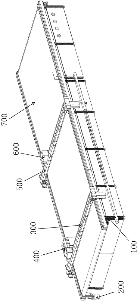
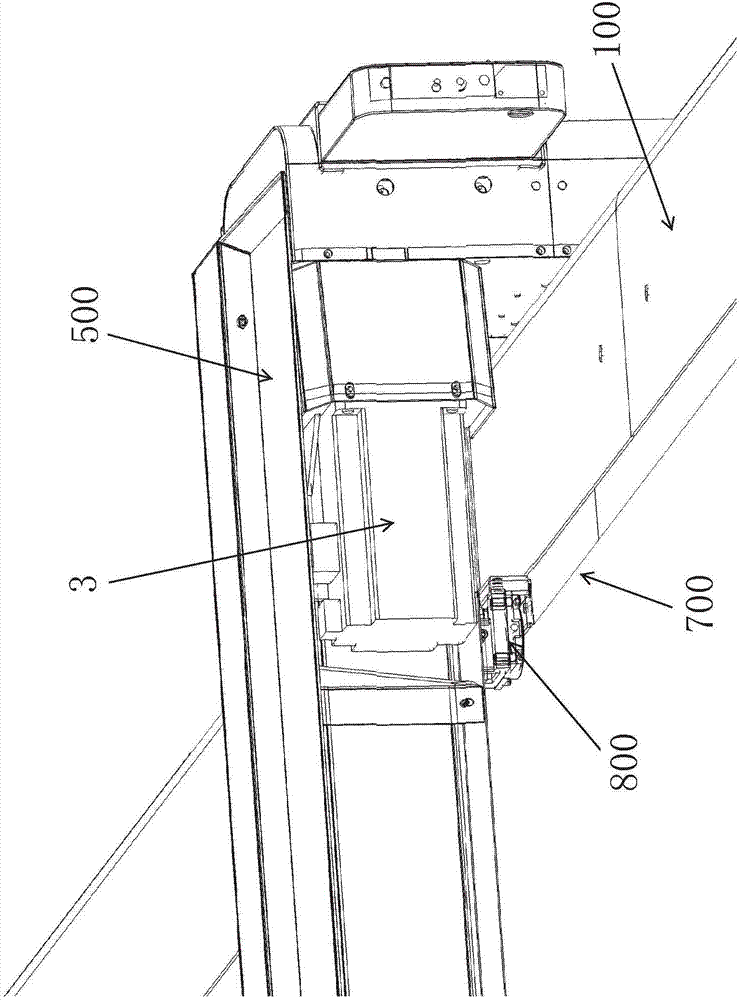
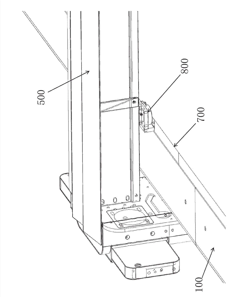
[0028] Such as figure 1 The shown cutting bed includes a frame 100 and a conveyor belt 700, on the frame 100, guide rails 11 are installed on the left and right sides of the conveyor belt 700, and the first crossbeam 300 and the second crossbeam 500 straddle the two sides respectively. On the side guide rail 11 and move back and forth along the guide rail 11, the scanning operation head 400 capable of moving left and right is installed on the first beam 300, and the cutting operation head 600 capable of moving left and right is installed on the second beam 500, as figure 2 , image 3 As shown, the clamping device 800 capable of clamping the left and right sides of the conveyor belt 700 is installed on the first beam 300 or the second beam 500 . Such as Figure 4 As shown, the conveyor belt 700 is wrapped around a driving roller 201 and a driven roller 205, the driving roller 201 and the driven roller 205 are installed at the front and rear ends of the frame 100 respectively...


PUM


Abstract

The invention discloses a cutting bed. By the use of a structure of multiple stations, a scanning head and a cutting head, pipeline automatic continuous operation of scanning, composing, cutting and collecting for irregular-outlined fabrics such as leather being cut with the cutting bed is achieved, and utilization rate of machines and processing efficiency are greatly improved. Further disclosed is a belt conveying method of the cutting bed. The cutting bed comprises a main conveying portion and an assisted conveying portion; in the main conveying portion, a conveyor belt is clamped through a clamping device arranged on a cross beam; a beam power motor of the cutting bed is used to drive the conveyor belt to convey materials; the structure is simple, and the cost is lowered. The assisted portion employs a three-phase motor to provide power, the conveyor belt is in a critical state of not moving while being able to move, the conveyor belt is controlled to move back and forth through the cross beam and experiences very low motion resistance, the conveyor belt hardly deforms, the fabrics never move when being conveyed, and conveying precision is improved.

Description

technical field [0001] The invention belongs to the technical field of cutting beds and cutting machines, and in particular relates to a cutting bed used for cutting leather and other materials with irregular contours and a conveying method thereof. Background technique [0002] At present, the application of cutting beds and cutting machines is becoming more and more widespread, and has spread to different fields such as clothing, shoes and hats, luggage and automotive interiors, and continues to affect the development of these industries, but most of the current applications are still in stand-alone operations Mode, that is, the operation mode using a single fixed working platform. In the prior art, the fixed working surface of the cutting bed or cutting machine is also improved into a conveyor belt-type working surface. Although the circularly conveyed working surface saves a little time-consuming unloading process, it still needs to stop when loading and laying materials...

Claims


Application Information

Patent Timeline
Patent Type & Authority Applications(China)
IPC IPC(8): B26D7/06
Inventor 方云科帅宝玉
Owner HANGZHOU ECHO SCI TECH
Why Eureka
Try Eureka