Mold releasing mechanism

A demoulding mechanism and demoulding technology, applied in the direction of presses, manufacturing tools, etc., can solve the problems of cumbersome operation, and achieve the effect of convenient operation, simple overall and fewer parts.

Active Publication Date: 2015-01-07
萍乡九州精密压机有限公司
View PDF7 Cites 10 Cited by
  • Summary
  • Abstract
  • Description
  • Claims
  • Application Information

AI Technical Summary

Problems solved by technology

In this way, when pressing different products each time, it is necessary to adjust both the demoulding stroke and the pressing stroke, which is cumbersome to operate

Method used


Image

  • Mold releasing mechanism
  • Mold releasing mechanism

Examples


Embodiment Construction

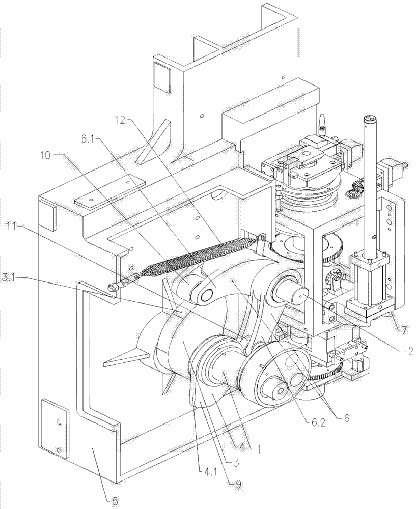
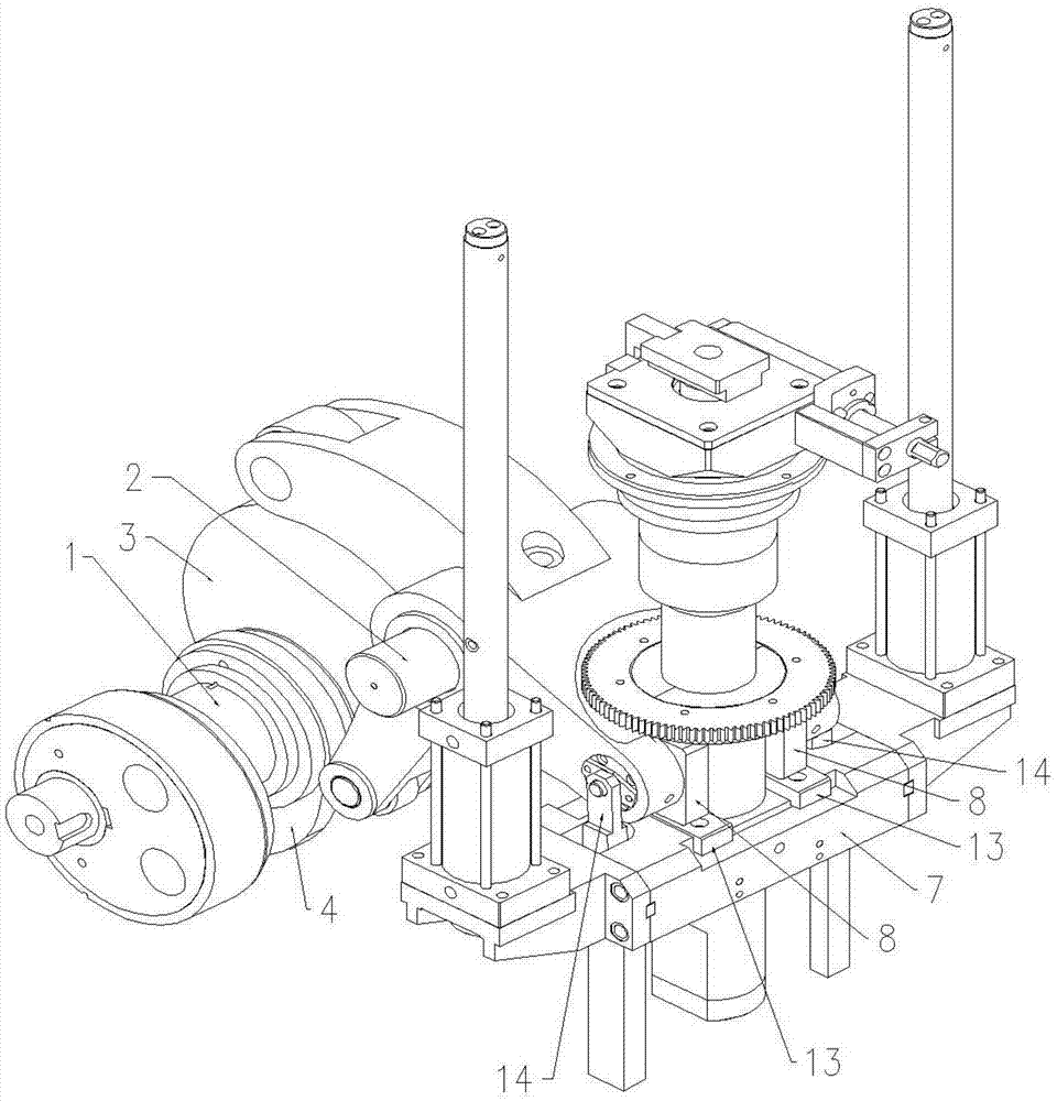
[0012] The present invention will be described in further detail below in conjunction with the accompanying drawings.

[0013] As shown in the figure, the demoulding mechanism of the present invention includes a driving main shaft 1, a demoulding lever shaft 2, a demoulding cam 3 and a reset cam 4 which are successively installed on the driving main shaft 1, which are rotatably mounted on the demoulding lever shaft 2 and The end is hinged on the demoulding lever 6 on the equipment frame 5, and is installed on the end of the demoulding lever 6 to press the equipment demoulding beam 7 downward under the action of the demoulding lever 6 to drive the equipment demoulding beam 7 to move downward. And realize the stripping briquetting block 8 of stripping.

[0014] Wherein the driving main shaft 1 and the demoulding lever shaft 2 are all installed on the equipment frame 5, and the demoulding cam 3 and the reset cam 4 are fastened on the driving main shaft 1 and linked with the drivi...


PUM


Abstract

A mold releasing mechanism comprises a driving spindle, a mold releasing lever shaft, a mold releasing cam, a reset cam, a mold releasing lever rotatably installed on the mold releasing lever shaft and hinged to a device machine frame, and a mold releasing press block installed at the end of the mold releasing lever, wherein the mold releasing cam and the reset cam are installed on the driving spindle and are arranged in parallel, the sharp ends of the mold releasing cam and the reset cam are opposite in orientation, a mold releasing roller in contact with a mold releasing cam profile is installed at the mold releasing sharp end of the mold releasing lever, a reset roller in contact with a reset cam profile is installed at the reset sharp end of the mold releasing lever, springs enabling the mold releasing roller and the reset roller to always abut against the mold releasing cam profile and the reset cam profile respectively are further arranged on the mold releasing lever, one end of each spring is installed on the mold releasing lever, and the other end of each spring is installed on the device machine frame. The mold releasing mechanism does not need to readjust a mold releasing stroke when different products are pressed.

Description

technical field [0001] The invention relates to a demoulding mechanism, which is used in dry powder compression molding equipment. Background technique [0002] At present, the more common dry powder pressing and molding equipment, because the pressing mechanism and the demoulding mechanism are interrelated, the sum of the pressing stroke and the demoulding stroke is the charging stroke, and for different products, the pressing strokes are different. Therefore, when the loading stroke remains unchanged, the demoulding stroke will change accordingly. [0003] For this reason, when pressing different products each time, the existing dry powder pressing molding equipment needs to readjust the demoulding stroke, and after the demoulding stroke is adjusted, the pressing stroke also needs to be adjusted accordingly. In this way, when pressing different products each time, both the demoulding stroke and the pressing stroke must be adjusted, which is cumbersome to operate. Conten...

Claims


Application Information

Patent Timeline
Patent Type & Authority Applications(China)
IPC IPC(8): B30B15/32
Inventor 彭涛李震宇陈磊
Owner 萍乡九州精密压机有限公司
Why Eureka
Try Eureka