Supercharge Your Innovation With Domain-Expert AI Agents!

screw conveyor

A screw conveyor, conveyor technology, applied in the field of conveyors

Active Publication Date: 2016-08-31
LAITRAM LLC
View PDF7 Cites 0 Cited by
  • Summary
  • Abstract
  • Description
  • Claims
  • Application Information

AI Technical Summary

Problems solved by technology

But one problem with positive drive helical systems is the crisp engagement and disengagement of the belt with the drive structure on the cage

Method used


Image

  • screw conveyor
  • screw conveyor
  • screw conveyor

Examples


Embodiment Construction

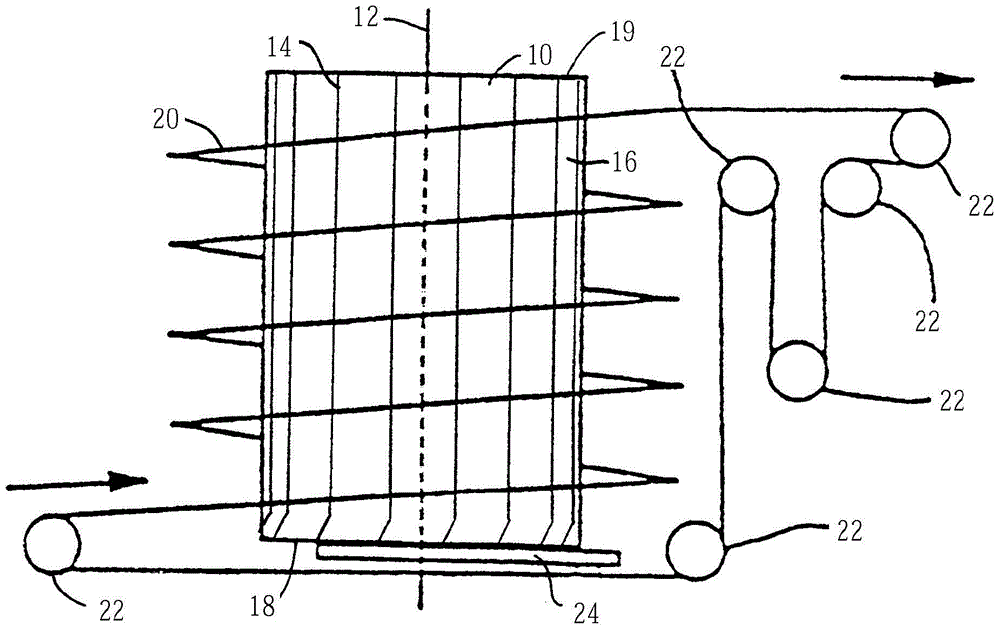
[0072] figure 1 A screw conveyor is schematically shown in . The screw conveyor comprises a drive tower 10 in the form of a cylindrical drum or cage, driven to rotate about a vertical axis 12 . The rotating tower has a plurality of parallel, generally vertical drive members 14 regularly spaced around its perimeter 16 . Each drive member extends in length between the bottom 18 and the top 19 of the tower. The conveyor belt 20 follows a multi-level helical path around the tower. The path is defined by a screw carryway or by a carryway at the bottom and stacker plates mounted on the belt. The inner edge of the belt positively engages the drive members which drive the belt upwards as the tower rotates. The belt travels around different receiving, idle and feeding sprockets 22 , which create a path back from the outlet at the top of the tower to the inlet at the bottom. Tower 10 is mounted at its base to a base 24 and is turned by an electric motor and gears (not shown).

[0...


PUM


Abstract

This invention relates to positive drive screw type conveyors and belts. A screw conveyor for positively driving a conveyor belt (20) along a helical path. The screw conveyor comprises a rotating cylindrical tower (10) with parallel drive members (14) extending on its perimeter from the bottom to the top of the tower. Each drive member includes an outwardly projecting ridge (28) varying in height from the base to the top of the tower. This height change facilitates entry and exit of the belt onto and from the tower and facilitates a firm positive drive engagement with the inner edge of the belt along most of its path along the tower. In another form, a conveyor belt has teeth (62) with guide surfaces (78, 79) at the inner edge of the belt. The teeth guide the drive members between the rows of belts into driving engagement with drive surfaces at the inner edges of the belts.

Description

[0001] This application is a divisional application of the application dated July 8, 2011, the application number is 201180033770.0, and the invention name is "forced drive screw conveyor and belt". technical field [0002] The present invention relates generally to power-driven conveyors, and more particularly to screw-type conveyors in which a conveyor belt is positively driven in a helical path around a rotating drive tower. Background technique [0003] Conveyor belts are commonly used to transport items such as food and other materials through cooled or heated environments. Screw conveyors, in which a conveyor belt follows a helical path that wraps around a central tower, drum, or cage, are used in refrigerators and ovens to provide long conveyors with a small footprint path. [0004] Some screw conveyors are constructed with a helical track supported on a central, non-rotating tower. Its conveyor belt is driven around the helical track by a plurality of drive sprocke...

Claims


Application Information

Patent Timeline
Patent Type & Authority Patents(China)
IPC IPC(8): B65G17/08B65G21/18
CPCB65G17/08B65G21/18B65G2812/02277B65G17/086B65G15/30
Inventor 卡斯帕尔·费德·塔斯马大卫·W·博格尔
Owner LAITRAM LLC
Features
  • R&D
  • Intellectual Property
  • Life Sciences
  • Materials
  • Tech Scout
  • Unparalleled Data Quality
  • Higher Quality Content
  • 60% Fewer Hallucinations
Learn More