Quantum communication method and system for terminal delay selection

A quantum communication and terminal technology, applied in the field of quantum communication, can solve problems such as the lack of quantum communication implementation solutions

Active Publication Date: 2019-09-06
SUZHOU UNIV
View PDF3 Cites 8 Cited by
  • Summary
  • Abstract
  • Description
  • Claims
  • Application Information

AI Technical Summary

Problems solved by technology

[0005] However, the existing quantum communication schemes are all based on the conditions that the receiver of the informati

Method used


Image

  • Quantum communication method and system for terminal delay selection
  • Quantum communication method and system for terminal delay selection
  • Quantum communication method and system for terminal delay selection

Examples


Embodiment 1

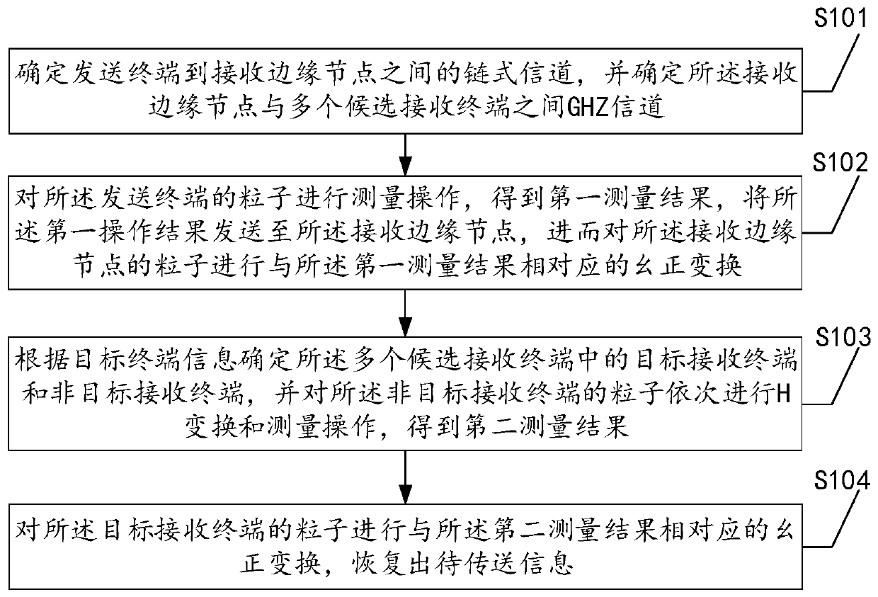
[0065] The following is an introduction to Embodiment 1 of a quantum communication method for terminal delay selection provided by this application, see figure 1 , embodiment one includes:

[0066] Step S101: Determine the chain channel between the sending terminal and the receiving edge node, and determine the GHZ channel between the receiving edge node and multiple candidate receiving terminals;

[0067] Specifically, this embodiment pre-constructs a quantum communication network, which includes a sending terminal, a receiving edge node, and multiple candidate receiving terminals. In addition, in order to realize long-distance communication, it may also include sending edge nodes and intermediate nodes. In the initially created quantum communication network, the sending terminal, sending edge node, intermediate node, and receiving edge node are connected through a Bell channel. To facilitate subsequent calculations, this embodiment determines the distance between the sending...

Embodiment 2

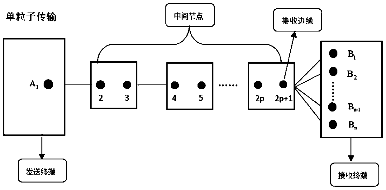
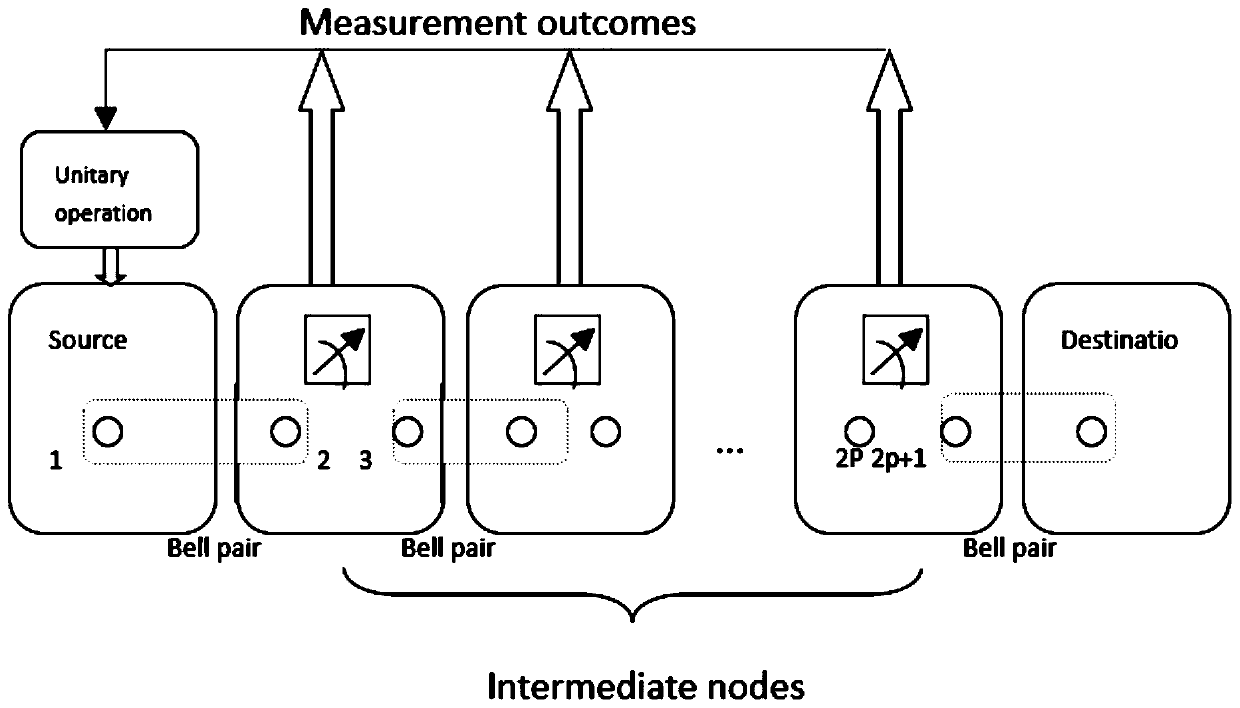
[0081] figure 2 It is a schematic diagram of the particle distribution of Alice, Bob (n candidate receiving terminals) and p intermediate nodes in the embodiment, refer to below figure 2 , to introduce the second embodiment. Embodiment two specifically includes:

[0082] Step S201: forming a GHZ channel;

[0083] Specifically, the receiving edge node and the candidate receiving terminal are connected by a Bell channel, and the specific form is as follows:

[0084]

[0085] in a in i Belongs to receiving edge nodes, b i belongs to each candidate receiving terminal i.

[0086] Receive edge node pair (a 1 ,a 2 ),(a 1 ,a 3 ),…(a 1 ,a n ) perform the CNOT operation respectively, where a 1 is the control qubit, a 2 ,a 3 ,...a n is the target qubit, as follows:

[0087]

[0088] where {x} is a 2 ,a 3 ,...,a n A sequence of 0, 1, Indicates the negation of {x}.

[0089] Receive edge node i pair particle a i Conduct {|0>,|1>} base measurement and send th...


PUM


Abstract

The invention discloses a quantum communication method and system for terminal delay selection, and the method comprises the steps: carrying out the measurement operation of particles of a sending terminal, and obtaining a first measurement result; performing unitary transformation corresponding to the first measurement result on the particles of the receiving edge node; sequentially performing Htransformation and measurement operation on the particles of the non-target receiving terminal to obtain a second measurement result; and carrying out unitary transformation corresponding to the second measurement result on the particles of the target receiving terminal, and recovering the to-be-transmitted information. Visibly, according to the scheme, under the condition that the receiving terminal is not completely determined, the particle state can start the transmission behavior, the receiving edge node can select the receiving terminal while the particle state is in channel transmission,and after the final receiving terminal is determined, the particles have transmitted most paths, so that the time delay is effectively reduced, and finally information receiving is completed. The quantum communication process of selecting the terminal is delayed under the condition that the terminal is uncertain, and the information transmission efficiency is improved.

Description

technical field [0001] The present application relates to the field of quantum communication, in particular to a quantum communication method and system for terminal delay selection. Background technique [0002] Quantum communication is an important branch of quantum information science and an earlier research field in quantum information. [0003] Quantum communication uses the quantum state as the information unit to realize the effective transmission of information. In order to transmit the unknown quantum state of an object, the information of the original object can be divided into two parts: classical and quantum information, which are transmitted to the receiver through the classical channel and the quantum channel respectively. The classical information is the sender’s measurement of the original object. The obtained quantum information is the rest of the information extracted by the sender in the measurement. After the receiver obtains these two kinds of informati...

Claims


Application Information

Patent Timeline
IPC IPC(8): H04B10/079H04B10/70
CPCH04B10/0795H04B10/70
Inventor 李太超钱盈家姜敏陈虹周刘蕾
Owner SUZHOU UNIV
Why Eureka
Try Eureka