
Three-dimension symmetrical vertical transformer

Active Publication Date: 2016-01-14
IND TECH RES INST
View PDF4 Cites 9 Cited by
  • Summary
  • Abstract
  • Description
  • Claims
  • Application Information

AI Technical Summary

Benefits of technology

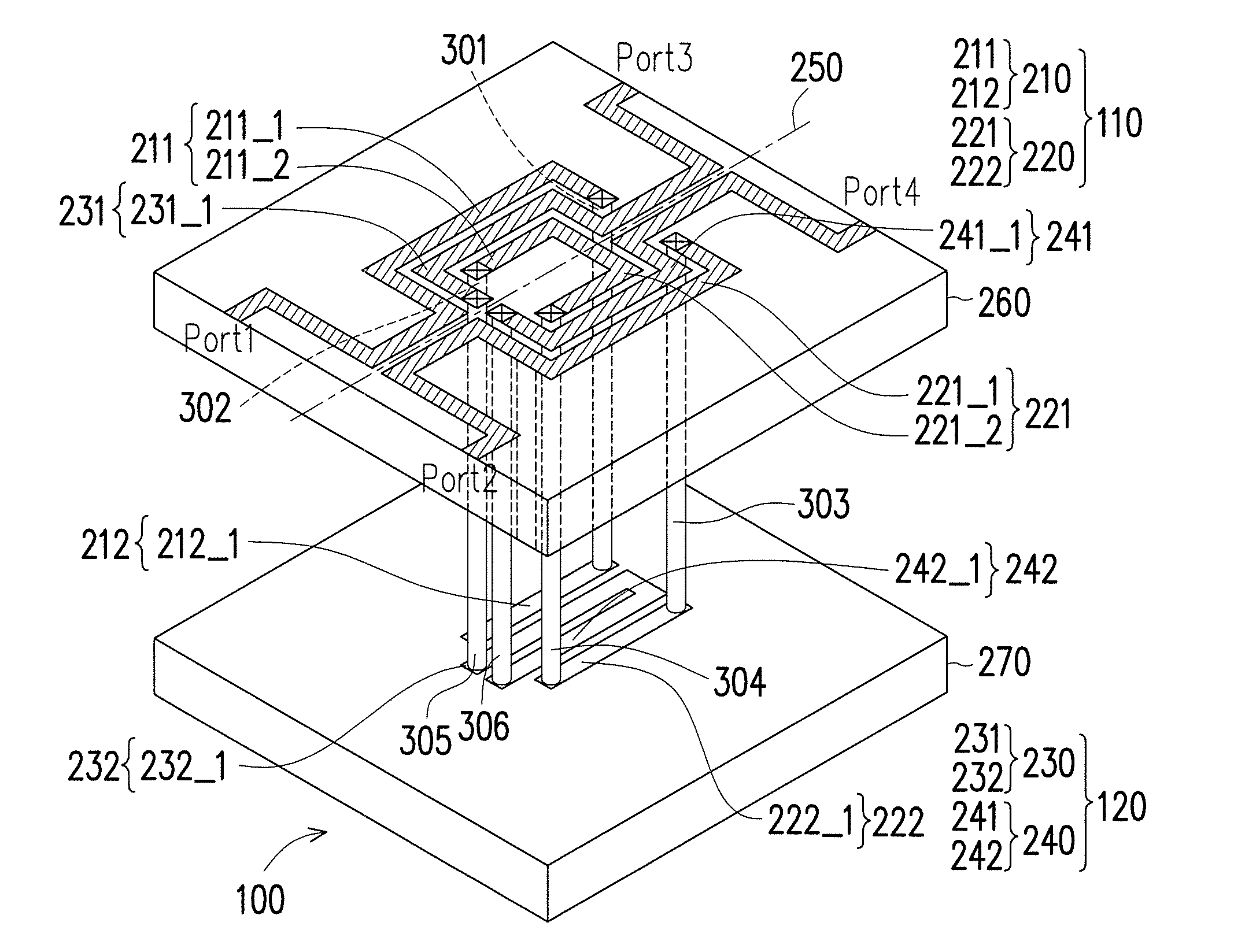
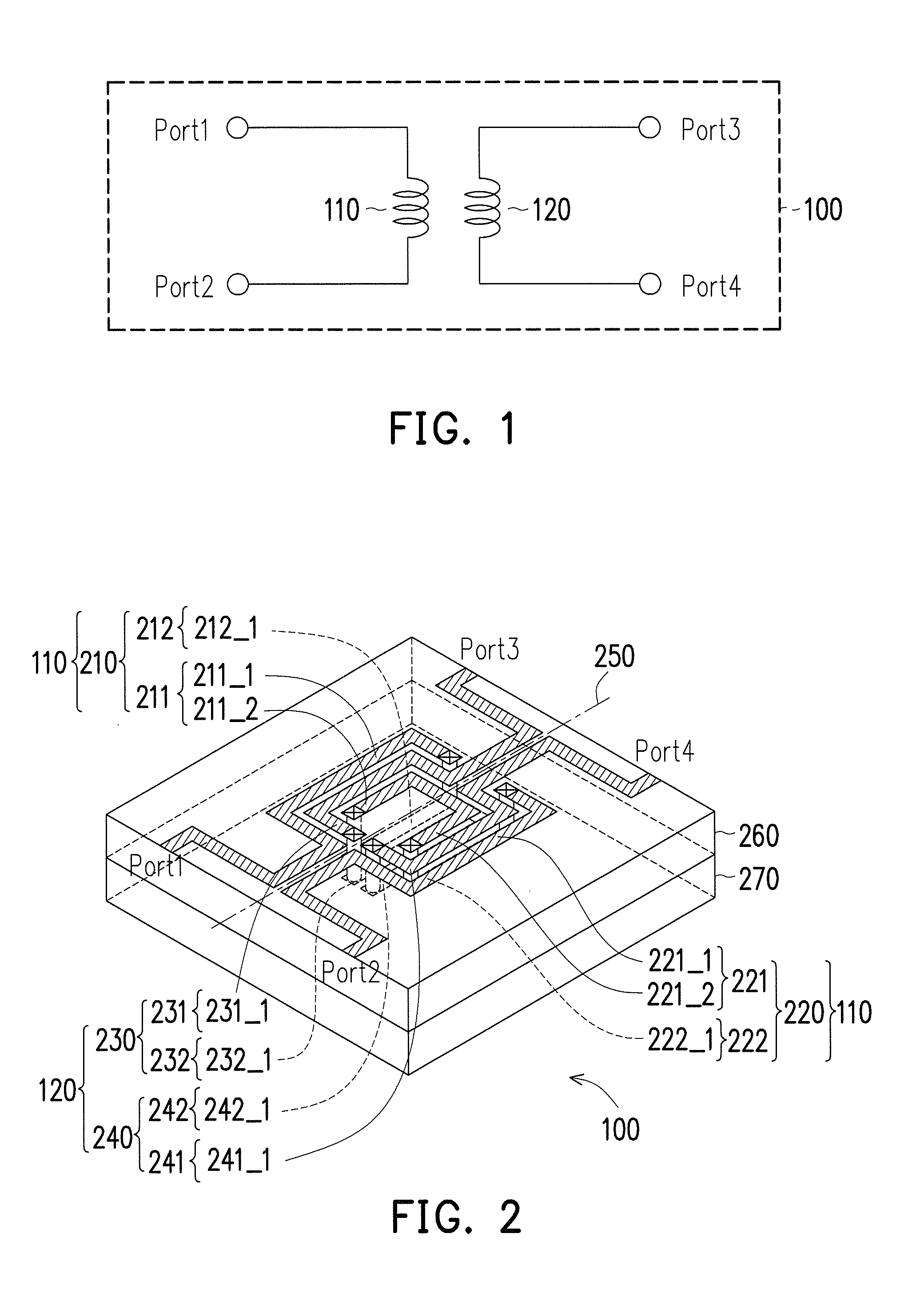
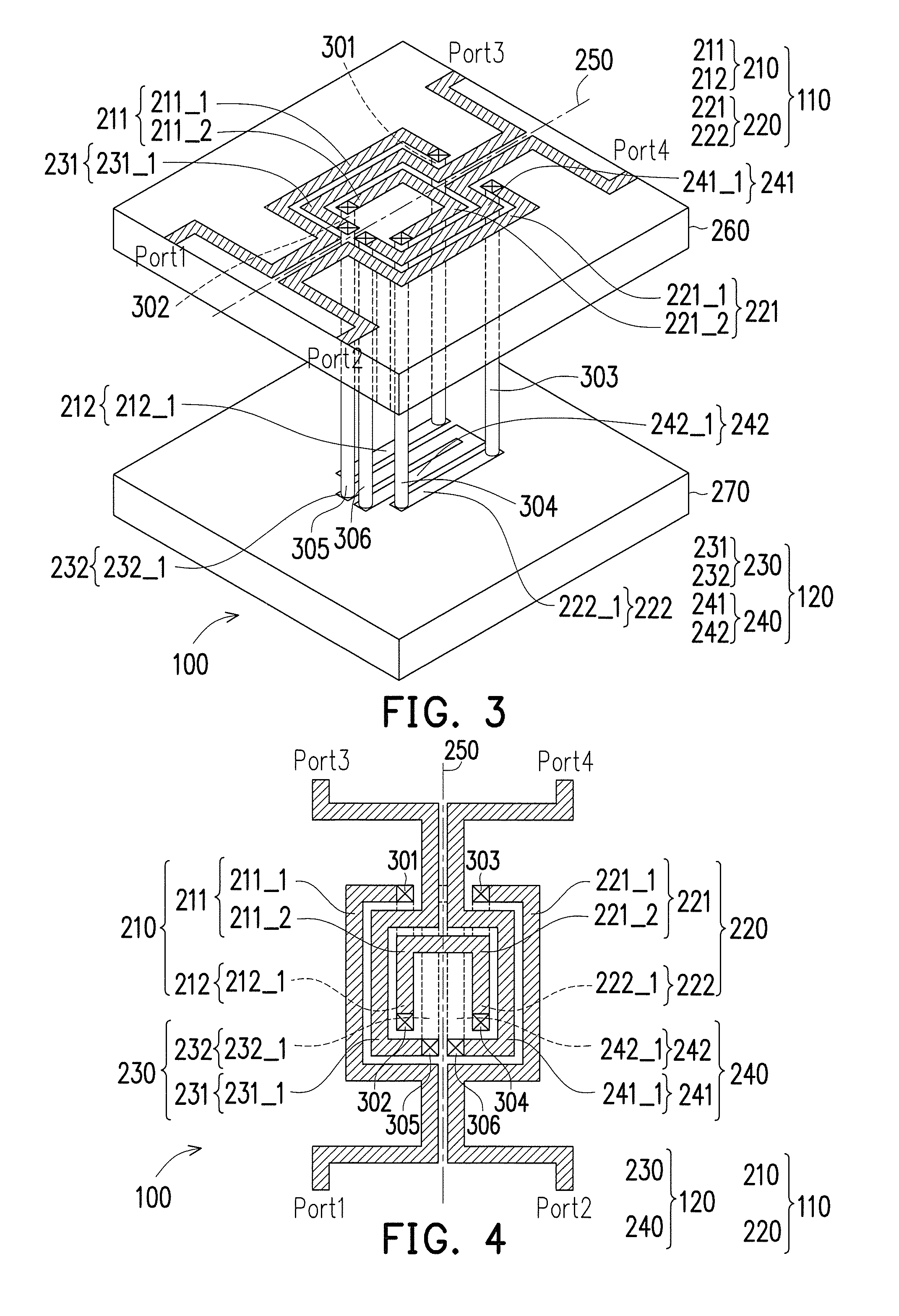
The patent describes a transformer design that includes two coils, one primary and one secondary. The primary coil has two electrical paths located on different sides of a straight line on a projection plane of the transformer. The secondary coil has two electrical paths also located on different sides of the straight line. The primary coil has terminals connected at the straight line called first and second ports, while the secondary coil has terminals called first and second ports. Each of the electrical paths has partial paths connected by through silicon vias (TSVs). The design allows for efficient coupling of magnetic fields and balanced current flow between the two coils.

Problems solved by technology

Although a number of external devices can be reduced by implementing the inductors and transformers in the chip, the passive devices in the chip usually occupy a large chip area, which increases cost of the FEOL.
Design of a semiconductor circuit often encounters a bottleneck, for example, an analog circuit and a digital circuit are not easy to be integrated through a system on chip (SoC) process, or even if the analog circuit and the digital circuit are integrated to the SoC, issues of high cost and being unable to achieve characteristic optimisation are encountered.
However, when packaging requirements become more complicated, the SiP technique also has a design bottleneck related to operation speed, power consumption, size, etc.
Besides consideration of area, there is still a technical issue related to noise.

Method used


Image

  • Three-dimension symmetrical vertical transformer
  • Three-dimension symmetrical vertical transformer
  • Three-dimension symmetrical vertical transformer

Examples


Embodiment Construction

[0020]A term “couple” used in the full text of the disclosure (including the claims) refers to any direct and indirect connections. For example, if a first device is described to be coupled to a second device, it is interpreted as that the first device is directly coupled to the second device, or the first device is indirectly coupled to the second device through other devices or connection means. Moreover, wherever possible, components / members / steps using the same referential numbers in the drawings and description refer to the same or like parts. Components / members / steps using the same referential numbers or using the same terms in different embodiments may cross-refer related descriptions.

[0021]FIG. 1 is a circuit schematic diagram of a transformer 100 according to an embodiment of the disclosure. The transformer 100 includes a primary coil 110 and a secondary coil 120. Based on transmission of an induced magnetic field, the primary coil 110 and the secondary coil 120 can transit...


PUM


Abstract

First and second paths of the primary-coil of the transformer are located at different sides of the symmetry-line. First terminals of the first and second paths are first and second ports of the primary-coil. Second terminals of the first and second paths are connected to each other. Two partial paths of the first path are connected to each other by TSV. Two partial paths of the second path are connected to each other by TSV. Third and fourth paths of the secondary-coil of the transformer are located on different sides of the symmetry-line. First terminals of the third and fourth paths are first and second ports of the secondary-coil. Second terminals of the third and fourth paths are connected to each other. Two partial paths of the third path are connected to each other by TSV. Two partial paths of the fourth path are connected to each other by TSV.

Description

CROSS-REFERENCE TO RELATED APPLICATION[0001]This application claims the priority benefits of U.S. provisional application Ser. No. 62 / 022,205, filed on Jul. 9, 2014 and Taiwan application serial no. 103130990, filed on Sep. 9, 2014. The entirety of each of the above-mentioned patent applications is hereby incorporated by reference herein and made a part of this specification.TECHNICAL FIELD[0002]The disclosure relates to a three-dimension symmetrical vertical transformer.BACKGROUND[0003]In an integrated circuit (IC) manufacturing process, various integrated passive devices (IPDs) are implemented in a chip through a front end of line (FEOL). Inductors and transformers are commonly used passive devices in the chip, and are widely applied to various radio frequency (RF) ICs, such as, a low noise amplifier (LNA), a voltage-controlled oscillator (VCO), an injection-locked frequency divider (ILFD), a power amplifier (PA), etc. Although a number of external devices can be reduced by implem...

Claims


Application Information

Patent Timeline
IPC IPC(8): H01F27/28H01F27/29
CPCH01F27/2804H01F2027/2809H01F27/2823H01F27/29H01F5/00
Inventor LI, SIH-HANLIN, CHIH-SHENG
Owner IND TECH RES INST
Learn More