
Construction method of antenna hoisting device of wireless base station

The technology of a hoisting device and a construction method, applied in the field of machinery, can solve problems such as danger and cumbersomeness, and achieve the effects of reducing wear, improving safety, and improving utilization rate

Active Publication Date: 2015-01-07
中邮建技术有限公司
View PDF5 Cites 4 Cited by
  • Summary
  • Abstract
  • Description
  • Claims
  • Application Information

AI Technical Summary

Problems solved by technology

Finally, when the antenna is hoisted to the pole, it is responsible for holding the big rope under the tower to prevent the uninstalled antenna from falling together with the big rope due to the influence of gravity. Therefore, during the outdoor construction of the wireless base station, at least 4 people must work together Only by cooperating can we complete this tedious and dangerous work

Method used


Image

  • Construction method of antenna hoisting device of wireless base station
  • Construction method of antenna hoisting device of wireless base station
  • Construction method of antenna hoisting device of wireless base station

Examples


Embodiment 1

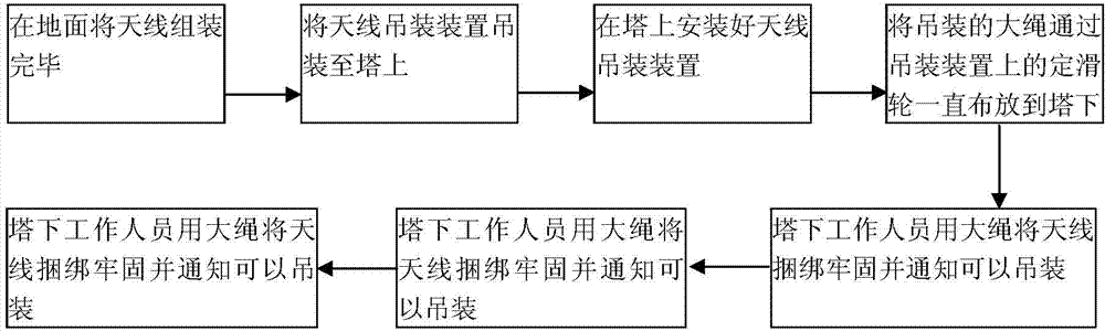
[0030] Such as figure 1 As shown, the present invention provides a construction method for an antenna hoisting device of a wireless base station, the method comprising the following steps:

[0031] Step 1: Assemble the antenna on the ground;

[0032] Step 2: The ground personnel cooperate with the construction personnel on the tower to lift the antenna hoisting device to the tower;

[0033] The construction personnel on the tower go up the tower, and the ground construction personnel cooperate with the staff on the tower to hoist the antenna hoisting device to the tower by using a large rope;

[0034] Step 3: The construction personnel install the antenna hoisting device in place on the tower;

[0035] The construction workers on the tower insert the antenna hoisting device into the hollow position of the iron tower pole, and use a wrench to tighten the three screws on the support rod fixing plate of the hoisting device, and shake it by hand to see if it is firmly installed;...

Embodiment 2

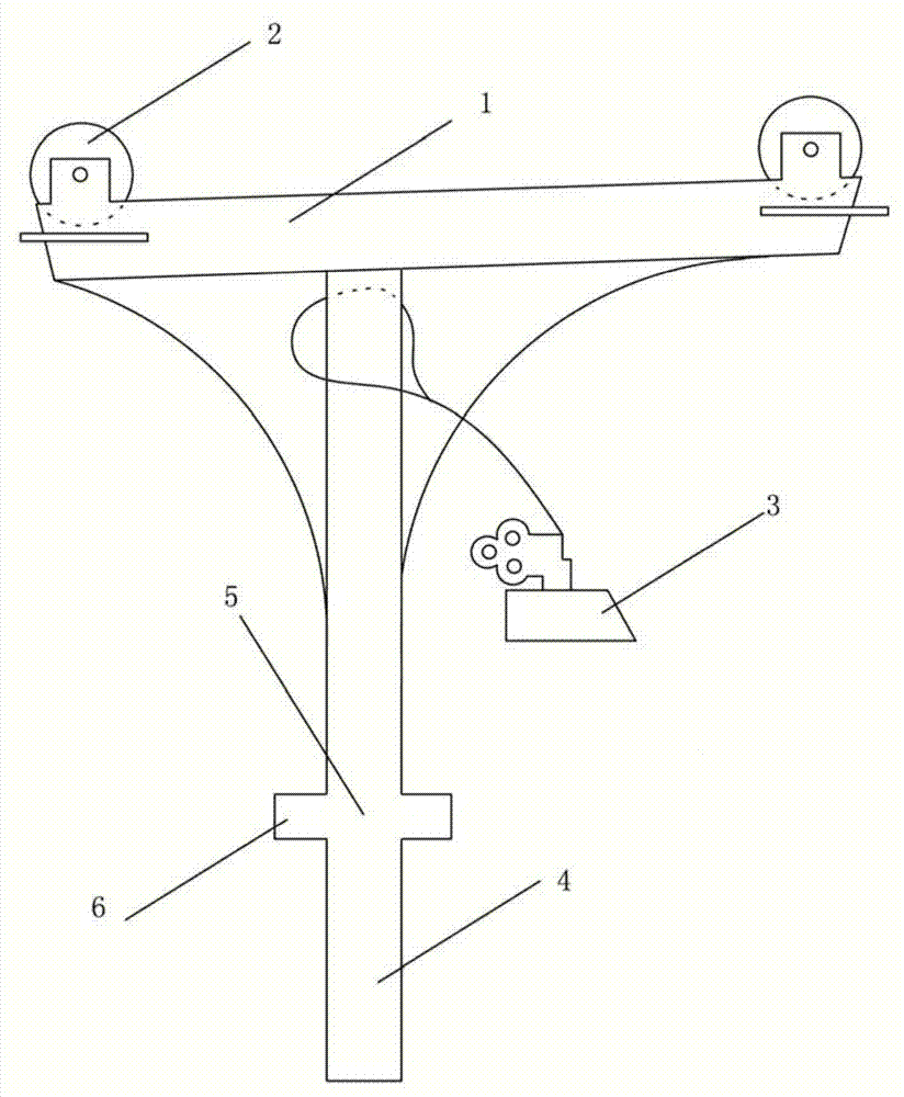
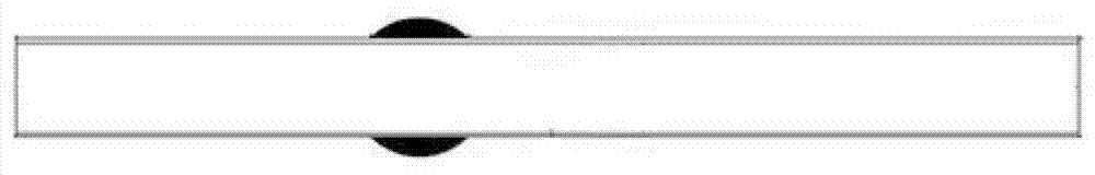
[0043] Such as Figure 2-6 As shown, the above-mentioned second step, the third step, the fourth step, and the antenna hoisting device in the fifth step of the present invention include a boom 1, an arc top fixed pulley 2, an arc flat iron 3, an anti-slip self-locking buckle 4, a hanging Arm support bar 5, support bar fixed plate 6 and boom latch 7. The boom 1 is positioned on the top of the boom support rod 5, and the boom 1 is welded to the boom support rod 5 by two arc-shaped flat irons 3. The arc top fixed pulley 2 is fixedly connected to the boom 1 through a screw, and the anti-skid self-locking buckle 4 is attached to the welding place of the boom support rod 5 and the arc flat iron 3 through a rope. The lower part of the rod 5 is welded to the support rod fixed disk 6, and the bottom of the supported rod fixed disk 6 is connected to the boom bolt 7 by welding. Said boom 1 is made of trough-type pig iron, with a groove in the middle, and a fixed pulley 2 with a diamete...


PUM

PropertyMeasurementUnit
Lengthaaaaaaaaaa
Widthaaaaaaaaaa
Lengthaaaaaaaaaa

Abstract

The invention discloses a construction method of an antenna hoisting device of a wireless base station. The method comprises the following steps: step 1, assembling an antenna on the ground; step 2, hoisting the antenna hoisting device to a tower by virtue of the cooperation of personnel on the ground and construction personnel on the tower, namely hoisting the antenna hoisting device to the tower by utilizing a big rope by virtue of the cooperation of the construction personnel on the ground and the construction personnel on the tower; step 3, installing the antenna hoisting device in place by the construction personnel on the tower; step 4, perpendicularly dropping off the big rope for hoisting the antenna through a crown block on the antenna hoisting device; step 5, pulling the big rope to hoist the antenna to a designated installation position; step 6, installing the antenna onto a holding bar on which the antenna needs to be installed, namely fixedly and firmly installing the antenna onto the designated holding bar through a reinforcing piece on the antenna. By adopting the method, the physical exhaustion of individual personnel in the antenna hoisting process can be reduced, the abrasion of the big rope is reduced, and manpower in the construction is reduced, the utilization rate of construction resources is increased and the safety can be improved.

Description

technical field [0001] The invention relates to a construction method for an antenna hoisting device of a wireless base station, and belongs to the technical field of machinery. Background technique [0002] At present, in the construction process of wireless base stations, hoisting antennas is a critical and highly risky task. Traditional antenna hoisting work requires at least four people to complete. That is: two people go up the tower and are responsible for installing the hoist for hanging the antenna. When the antenna is hoisted to the tower, the two people cooperate to install the antenna on the designated pole. The two workers under the tower are responsible for binding the antenna. After binding, one person is responsible for pulling the large rope, and the other is responsible for pulling the large rope, controlling the trajectory of the antenna during hoisting, so as to prevent the antenna from colliding with the tower body. Finally, when the antenna is hoisted ...

Claims


Application Information

Patent Timeline
IPC IPC(8): B66C25/00
CPCB66C25/00B66C2700/00
Inventor 陈铭魏雷郭复胜陶珩
Owner 中邮建技术有限公司
Learn More